
Single-phase switched reluctance motor capable of alternating operation through adoption of direct current motor principle and reluctance motor principle

A switched reluctance motor, alternating operation technology, applied in electrical components, electromechanical devices, etc., can solve the problems of single-phase SR motor without self-starting, short driving reluctance torque area, low utilization rate, etc., to improve power Density and operating efficiency, reducing torque ripple, realizing the effect of energy recovery

Inactive Publication Date: 2017-09-29
杭州小爻科技有限责任公司
View PDF2 Cites 5 Cited by
  • Summary
  • Abstract
  • Description
  • Claims
  • Application Information

AI Technical Summary

Problems solved by technology

[0004] In order to overcome the drive control of the SR motor in the prior art, the region of the driving reluctance torque generated by the electrification of the stator winding is short and the utilization rate is reduced; and the single-phase SR motor has no self-starting function, and the torque ripple is relatively large during operation. big disadvantage

Method used


Image

  • Single-phase switched reluctance motor capable of alternating operation through adoption of direct current motor principle and reluctance motor principle
  • Single-phase switched reluctance motor capable of alternating operation through adoption of direct current motor principle and reluctance motor principle
  • Single-phase switched reluctance motor capable of alternating operation through adoption of direct current motor principle and reluctance motor principle

Examples


Embodiment Construction

[0021] Its embodiment will be further described below in conjunction with accompanying drawing.

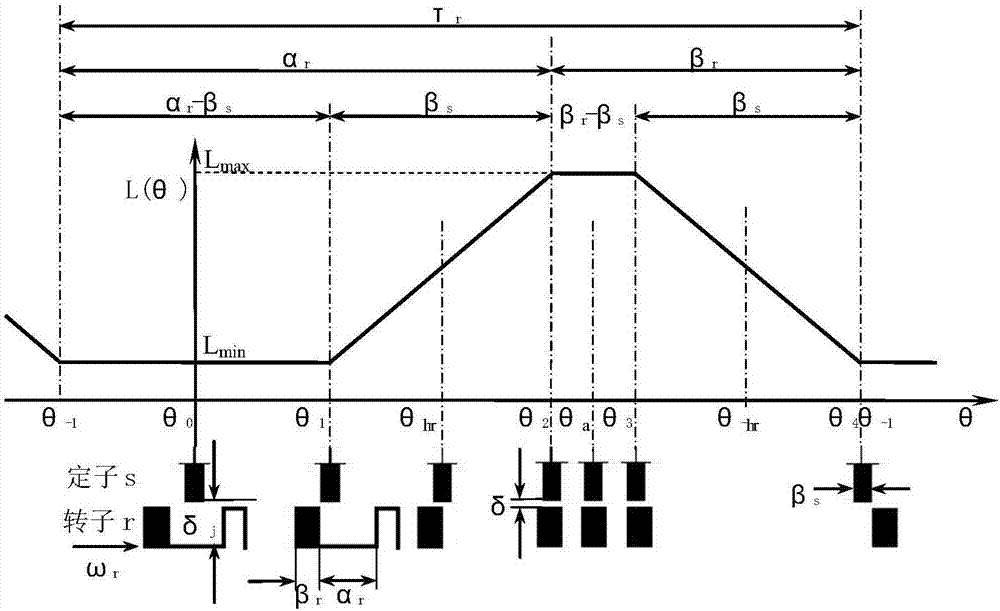
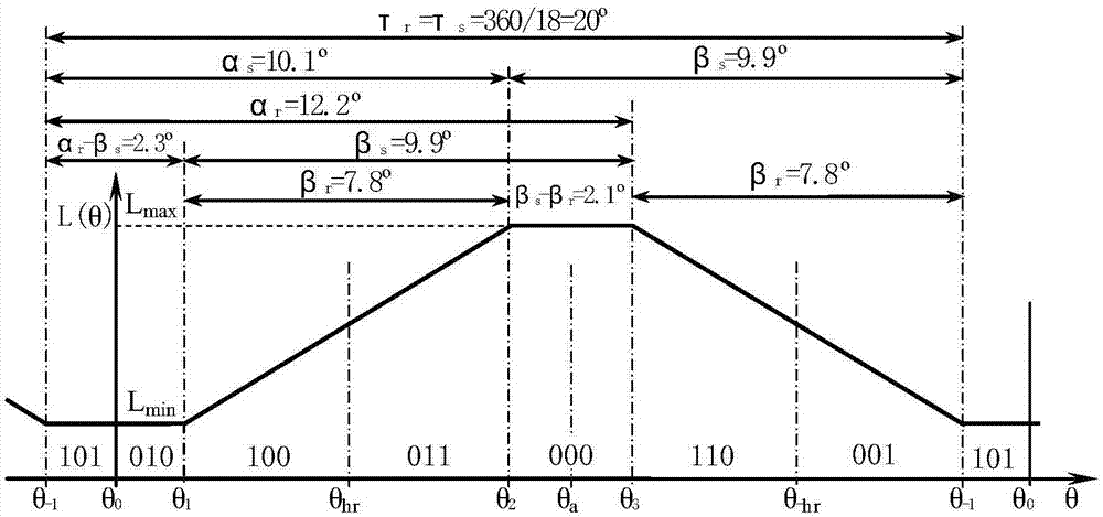
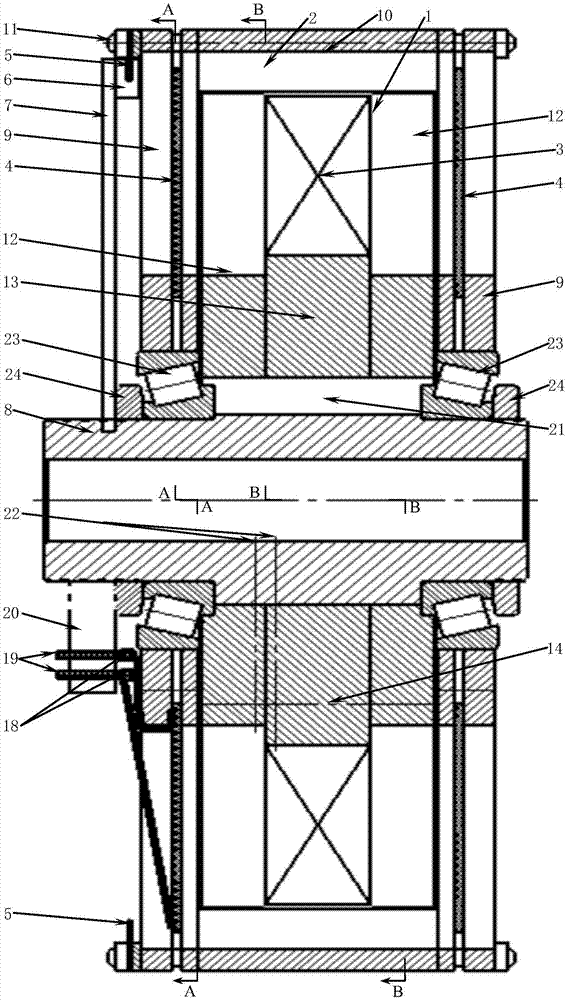
[0022] refer to Figure 2 ~ Figure 6 , a single-phase SR motor that uses two motor principles of DC and reluctance to operate alternately, and needs to use the attached figure 1 The relationship between the linear inductance L of the SR motor and the rotor displacement angle θ is shown, and the characteristic point area where the motor operates according to the two principles of DC and reluctance is analyzed, so as to adjust the number of stator and rotor poles and the salient pole distance. Structural parameters, to expand the operating area that can generate driving torque according to the two motor principles, and improve various related operating performances. In order for the stator to be excited, all the salient poles of the stator and rotor act on each other, and the number of poles or pole pitch angles of the stator and rotor are required to be equal; in order to improve ...


PUM


Abstract

The present invention provides a single-phase switched reluctance motor capable of alternating operation through adoption of a direct current motor principle and a reluctance motor principle. The single-phase switched reluctance motor is a stator and rotor structure having double salient poles, the stators are internally provided with excitation windings, the rotor salient poles are provided with corresponding armature windings capable of allowing the motor to run according to the direct current motor principle, the current direction of the rotor armature windings is in tangent relation with the magnetic line of a magnetic field formed by stator excitation windings, a code disc capable of association with stator salient pole distances and rotor salient pole distances and reflection of position angles of feature points at the position where the rotors are rotated, and optocouplers are employed to perform direct detection to control the switching of two motor running modes of magnetic resistance and direct current. The motor power density and the running efficiency are improved, and the torque generated through alternating operation according to the direct current motor principle and the reluctance motor principle is overlapped to reduce the torque ripple.

Description

technical field [0001] The invention belongs to the field of single-phase switched reluctance motors, in particular to a single-phase switched reluctance motor involving two working principles of a switched reluctance SR motor and a DC motor. Background technique [0002] Electric motors consume more than 60% of the entire power grid. With the deepening of energy saving and emission reduction requirements, it is of great significance to improve the efficiency of motors, especially in the field of speed control motor control. [0003] As a means of energy-saving and emission-reducing transportation, electric vehicles have been widely valued by countries all over the world, and are recognized as energy-saving and environmentally friendly future vehicles. Any type of electric vehicle included needs to use the motor as an actuator to drive the wheels. Therefore, improving motor performance and reducing costs are one of the primary tasks to improve the cost performance of variou...

Claims


Application Information

Patent Timeline
Patent Type & Authority Applications(China)
IPC IPC(8): H02K29/03H02K29/10
CPCH02K29/03H02K29/10H02K2213/03
Inventor 王金懿蒋伟陈捷雷王贵明
Owner 杭州小爻科技有限责任公司
Learn More