Preparation method for MoS2@C composite electrode material with lignin as carbon source
A composite electrode and lignin technology, used in electrode manufacturing, battery electrodes, electrode heat treatment, etc., can solve the problems of volume change and unstable electrochemical performance, and achieve the effect of improving contact area, particle uniformity, and avoiding volume change
- Summary
- Abstract
- Description
- Claims
- Application Information
AI Technical Summary
Problems solved by technology
Method used
Image
Examples
Embodiment 1
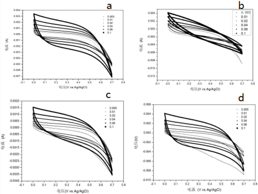
[0029] Dissolve 0.5g of sodium lignosulfonate in 20ml of deionized water, and ultrasonically dissolve. Take 40ml of isopropanol and place it in a 150w ultrasonic water bath, use a 30ml syringe to inject the sodium lignosulfonate aqueous solution into the isopropanol at a speed of 20ml / h by means of an automatic sampler. A suspension of lignin microspheres was obtained. Weigh 0.151g of thiourea and 0.237g of sodium molybdate into the suspension, and place the mixture in an autoclave. The reaction kettle was placed in a high-temperature oven at 180°C for 8 hours of reaction. After cooling, the reactant is centrifuged and washed to obtain lignin microsphere powder with molybdenum disulfide. The product powder was dried in a vacuum oven at 60°C for 24 hours to obtain the dry product MoS 2 @Lignin nanosphere powder. Will dry MoS 2 @Lignin nanosphere powder placed in N 2 Calcined in a tube furnace in the atmosphere (heat up to 300°C at a speed of 5°C / min, then rise to 500°C at...
Embodiment 2
[0031] Others are the same as in Example 1, except that the reaction temperature is 200°C. The resulting MoS 2 @C composite particles have better dispersibility, and the particle diameter is about 1 μm. However, the molybdenum disulfide coating is general.
Embodiment 3
[0033] Others are the same as Example 2, except that the consumption of sodium lignosulfonate is 1g. The resulting MoS 2 The particle diameter of @C composite material is about 1 μm. Molybdenum disulfide is also better coated, Figure 4 b and d are the constant current charge and discharge diagram and specific capacitance diagram of embodiment 3. It can be seen from the figure that the specific capacity retention rate of Example 3 is not high, and its specific capacity decays rapidly with the increase of charge and discharge times.
PUM
| Property | Measurement | Unit |
|---|---|---|
| Diameter | aaaaa | aaaaa |
| Specific capacitance | aaaaa | aaaaa |
Abstract
Description
Claims
Application Information
 - R&D
- Intellectual Property
- Life Sciences
- Materials
- Tech Scout
- Unparalleled Data Quality
- Higher Quality Content
- 60% Fewer Hallucinations
Browse by: Latest US Patents, China's latest patents, Technical Efficacy Thesaurus, Application Domain, Technology Topic, Popular Technical Reports.
© 2025 PatSnap. All rights reserved.Legal|Privacy policy|Modern Slavery Act Transparency Statement|Sitemap|About US| Contact US: help@patsnap.com


