A rotary gas foaming device

A gas foaming and rotating technology, applied in the field of foaming aluminum production equipment, can solve the problems of uneven foaming, achieve high foaming rate, increase the contact area, and promote the effect of foaming uniformity

Active Publication Date: 2018-08-24
浙江金汤塑胶科技股份有限公司
View PDF1 Cites 0 Cited by
  • Summary
  • Abstract
  • Description
  • Claims
  • Application Information

AI Technical Summary

Problems solved by technology

[0005] The purpose of the present invention is to address the deficiencies of the prior art, through the high-pressure foaming gas to output the aluminum liquid at high pressure, the aluminum liquid passes through the gas curtain, and the aluminum liquid is injected into the foaming gas at high pressure and fully contacted, so as to realize the aluminum liquid Uniform foaming, solving the problem of uneven foaming in the prior art

Method used


Image

  • A rotary gas foaming device
  • A rotary gas foaming device
  • A rotary gas foaming device

Examples


Embodiment 1

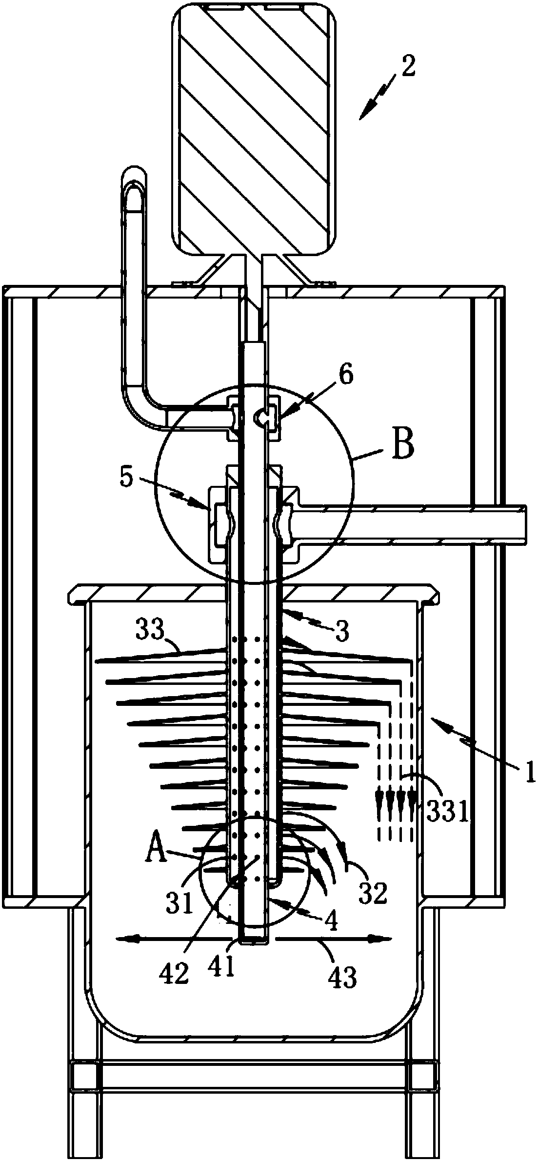
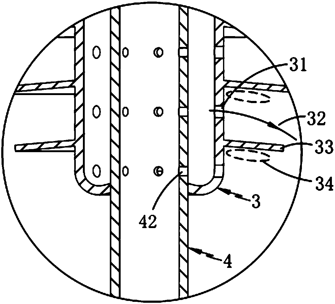
[0035] Such as figure 1 , 2 As shown in and 3, a rotary gas foaming device includes a foaming chamber 1, a drive assembly 2 fixedly arranged above the foaming chamber 1, an aluminum liquid output pipe 3 and a gas output pipe 4, and the aluminum liquid output The tube 3 is installed on the top of the foaming chamber 1 by rotating in the vertical direction, and its interior is hollow, and communicates with the interior of the foaming chamber 1 through a plurality of liquid outlet holes 31 opened thereon; The gas output pipe 4 runs through the aluminum liquid output pipe 3 and is sealed and fixedly connected to its axial two ends, one end of the gas output pipe 4 is fixedly connected to the drive assembly 2, and the other end is closed. A gas nozzle 41 is opened above; the foaming gas inside the gas output pipe 4 compresses the aluminum liquid inside the aluminum liquid output pipe 3 through a plurality of gas compression ports 42 opened thereon, and is sprayed out through the l...

Embodiment 2

[0037] The inventor believes that in order to better implement the technical solution, it is necessary to further clarify the implementation manner, so the inventor described the second embodiment on the basis of the first embodiment.

[0038] Such as figure 1 , 2 As shown in and 3, a rotary gas foaming device includes a foaming chamber 1 and a drive assembly 2 fixedly arranged above the foaming chamber 1, and also includes:

[0039] The aluminum liquid output pipe 3, the aluminum liquid output pipe 3 is installed on the top of the foaming chamber 1 by rotating in the vertical direction, and its interior is hollow, and passes through a plurality of liquid outlet holes 31 and the The interior of the above-mentioned foaming chamber 1 is connected; the aluminum liquid inside the aluminum liquid output pipe 3 is sprayed out along the liquid outlet hole 31 and forms a liquid streamline 32 around it, and the liquid streamline 32 passes through the gas curtain 43 in a parabola shape...


PUM


Abstract

The invention relates to a rotary gas foaming device, which includes a foaming chamber and a driving assembly fixedly arranged above the foaming chamber, and also includes an aluminum liquid output pipe and a gas output pipe, and the aluminum liquid output pipe is along the vertical direction Rotatingly installed on the top of the foaming chamber, its interior is hollow and set, and communicates with the interior of the foaming chamber through a plurality of liquid outlet holes opened on it; the gas output pipe runs through the aluminum The liquid output pipe is sealed and fixedly connected with both ends of the axial direction, one end of the gas output pipe is fixedly connected with the drive assembly, and the other end is closed, and a gas nozzle is opened above the end; The aluminum liquid is output at high pressure, and then dispersed by the gas curtain. The aluminum liquid and the foaming gas are fully contacted many times to realize the gas foaming of the aluminum liquid and solve the problem of uneven foaming in the prior art.

Description

technical field [0001] The invention relates to the technical field of foamed aluminum production equipment, in particular to a rotary gas foaming device. Background technique [0002] The application of aluminum continues to increase due to its low density, high stiffness, corrosion resistance and good formability. This trend is particularly evident in the automotive industry, household appliances and construction industries, where there is a huge demand for aluminum with complex shapes and higher strength; It is to add a certain foaming agent into molten aluminum or aluminum alloy. The foaming agent decomposes at high temperature, releases gas, stays in the melt, and forms metal foam after solidification. The pores of the aluminum foam produced by this method are independent of each other and can be used as sound-absorbing cushioning materials, but its disadvantages are that the distribution of pores is poor, the operation is difficult, and the production is uncontrollabl...

Claims


Application Information

Patent Timeline
Patent Type & Authority Patents(China)
IPC IPC(8): C22C1/08
CPCC22C1/08C22C1/086
Inventor 黄招凤
Owner 浙江金汤塑胶科技股份有限公司
Why Eureka
Try Eureka