
Flue gas purification and waste heat recovery system

A waste heat recovery system and flue gas purification technology, applied in the field of environmental protection systems, can solve the problems of poor temperature response ability of the temperature storage wall, large filter load of ceramic filter structure, waste and other problems, so as to prevent the temperature from rising instantaneously and prevent heat Shock phenomenon damage, reduce filter pressure effect

Active Publication Date: 2017-09-01
龙游县金怡热电有限公司
View PDF6 Cites 1 Cited by
  • Summary
  • Abstract
  • Description
  • Claims
  • Application Information

AI Technical Summary

Problems solved by technology

[0003] But this kind of flue gas dust removal device has the following disadvantages: 1) The high temperature dusty flue gas is blown directly to the ceramic filter structure. If it is in the interval production mode, the high temperature dusty flue gas will enter the flue gas purification and dust removal system intermittently, repeatedly The high temperature and cooling will reduce the life of the ceramic filter structure
2) The ash removal operation of the ceramic filter structure is difficult to carry out, and there is too much ash attached to the ceramic filter structure, which makes continuous production difficult
3) There are many grades of particles in the flue gas, and the content is large, and the filtration load on the ceramic filter structure is too large
[0004] In order to prevent the internal temperature of the flue gas purification and waste heat recovery system from changing violently repeatedly, some scholars also set up a temperature storage wall structure inside the system, such as at the entrance, so as to achieve the function of regulating temperature, but the temperature response of this temperature storage wall is limited. The ability is very poor, and it cannot respond quickly to short-term temperature changes, and its own energy storage is often wasted after stopping work, and heat recovery cannot be performed

Method used


Image

  • Flue gas purification and waste heat recovery system
  • Flue gas purification and waste heat recovery system

Examples


Embodiment Construction

[0028] The technical solutions in the embodiments of the present invention will be clearly and completely described below with reference to the accompanying drawings in the embodiments of the present invention. Obviously, the described embodiments are only a part of the embodiments of the present invention, but not all of the embodiments. Based on the embodiments of the present invention, all other embodiments obtained by those of ordinary skill in the art without creative efforts shall fall within the protection scope of the present invention.

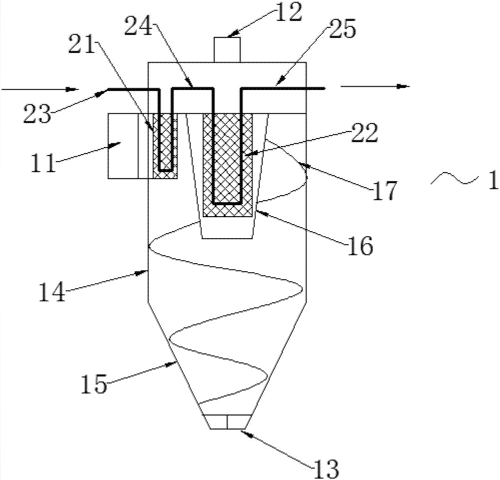
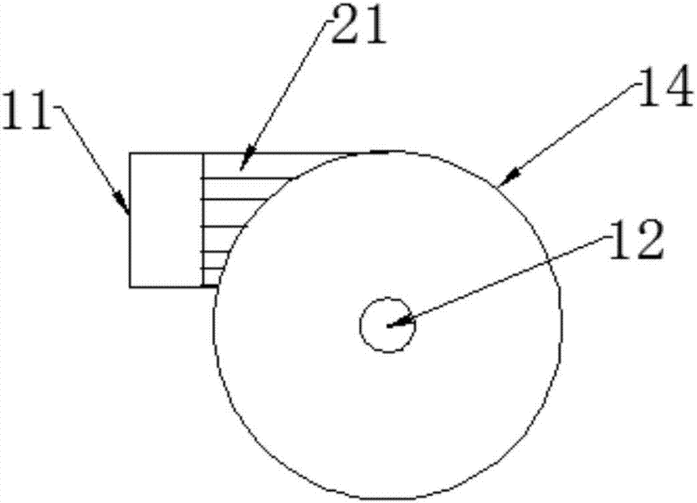
[0029] A flue gas purification and waste heat recovery system, the system includes a cyclone 1, the shell of the cyclone 1 includes an upper cylindrical barrel 14, a lower cone 15, a thermal insulation layer attached to the inner wall of the shell, There is also a partition in the shell, which divides the inside of the shell into a dust collection chamber and a clean air chamber. The overflow port 12 of the cyclone 1 is located above t...


PUM


Abstract

The invention provides a flue gas purification and waste heat recovery system which comprises a cyclone; a housing of the cyclone comprises an upper cylindrical barrel body and a lower cone; a partition plate is arranged in the housing and divides the housing into a dust collection chamber and a gas purification chamber; an overflow port of the cyclone is located above the gas purification chamber; an impurity discharge port of the cyclone is located below the dust collection chamber; a ceramic filtering membrane tube is arranged on the partition plate and stretches towards the dust collection chamber; a preheating exchanger is arranged in a gas inlet of the cyclone; a main heat exchanger is arranged in the ceramic filtering membrane tube; and a water inlet pipe, the preheating exchanger, a connecting pipe, the main heat exchanger and a water outlet pipe are sequentially connected. When high-temperature flue gas enters the flue gas purification and waste heat recovery system, the high-temperature flue gas exchanges heat with the preheating exchanger, and water in the preheating exchanger is pre-heated and then enters the main heat exchanger, by this time, a temperature difference between the temperature of the flue gas and the temperature in the main heat exchanger is reduced, and the temperature difference between the interior and the exterior of the ceramic filtering membrane tube is reduced, thus the ceramic filtering membrane tube is effectively prevented from being damaged by thermal shock.

Description

technical field [0001] The invention relates to an environmental protection system, in particular to a flue gas purification and waste heat recovery system. Background technique [0002] Metallurgy, electric power, building materials and other industrial kilns will emit a large amount of dusty flue gas during production, which will not only have a huge impact on air quality and visibility, but also the fine particles in it will cause great harm to the respiratory system and seriously threaten people's health. healthy. Therefore, the purification and dust removal of flue gas has become a necessary measure in industrial production. CN206198879U discloses a flue gas dust removal device, in figure 1 and figure 2 It is shown that the flue gas dedusting device includes a shell, a thermal insulation layer attached to the inner wall of the shell, a flower plate that divides the shell into a dust collection chamber and a clean air chamber, and heat exchange elements and a measuri...

Claims


Application Information

Patent Timeline
IPC IPC(8): F27D17/00B01D50/00
CPCF27D17/004F27D17/008F27D2017/009B01D50/20Y02P10/25Y02P80/15
Inventor 陈欢欢施彩莲段国生孙东燕严振国钱荣伟张小伟段鹏飞叶宁
Owner 龙游县金怡热电有限公司
Learn More