


Quick Research
Generate reliable direction feasibility study reports for your R&D in just a few steps.

Technical Q&A
Discover and master advanced knowledge NOW. Basics, ideas, possibilities, all at once.

Find Solutions
As an expert in R&D theories, this can generate solutions to your technical problems instantly.

Evaluate Feasibility
Analyze your overall solution with one click, know your potential R&D risks in advance.

Monitor Landscape
Get weekly tech updates, stay abreast of the latest tech innovations and key insights.
Horizontal slurrying device for rare earth mineral
A rare earth mine, horizontal technology, applied in the direction of transportation and packaging, improvement of process efficiency, mixer with rotating container, etc., can solve the problems of many parts, troublesome maintenance and repair, etc., and achieve low manufacturing cost and convenient maintenance and repair , easy to manufacture the effect
- Summary
- Abstract
- Description
- Claims
- Application Information
AI Technical Summary
Problems solved by technology
Method used
Image

Examples
Embodiment 1
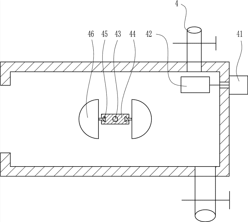
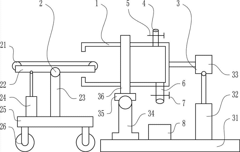
[0027] A horizontal pulping device for rare earth ore, such as Figure 1-3As shown, it includes a mixing drum 1, a conveying device 2, a rotating device 3, an inlet pipe 4, an inlet valve 5, a discharge pipe 6, a discharge valve 7 and a receiving cylinder 8; There is a feed inlet, a conveying device 2 is set on the left side of the mixing drum 1, a rotating device 3 is set on the lower right of the mixing drum 1, a water inlet pipe 4 is welded on the right part of the top of the mixing drum 1, and a water inlet pipe 4 is installed on it. Water inlet valve 5, the right part of mixing drum 1 bottom is welded with discharge pipe 6, and discharge valve 7 is installed on the discharge pipe 6, and material receiving cylinder 8 is arranged on the below of discharge pipe 6.
Embodiment 2
[0029] A horizontal pulping device for rare earth ore, such as Figure 1-3 As shown, it includes a mixing drum 1, a conveying device 2, a rotating device 3, an inlet pipe 4, an inlet valve 5, a discharge pipe 6, a discharge valve 7 and a receiving cylinder 8; There is a feed inlet, a conveying device 2 is set on the left side of the mixing drum 1, a rotating device 3 is set on the lower right of the mixing drum 1, a water inlet pipe 4 is welded on the right part of the top of the mixing drum 1, and a water inlet pipe 4 is installed on it. Water inlet valve 5, the right part of mixing drum 1 bottom is welded with discharge pipe 6, and discharge valve 7 is installed on the discharge pipe 6, and material receiving cylinder 8 is arranged on the below of discharge pipe 6.
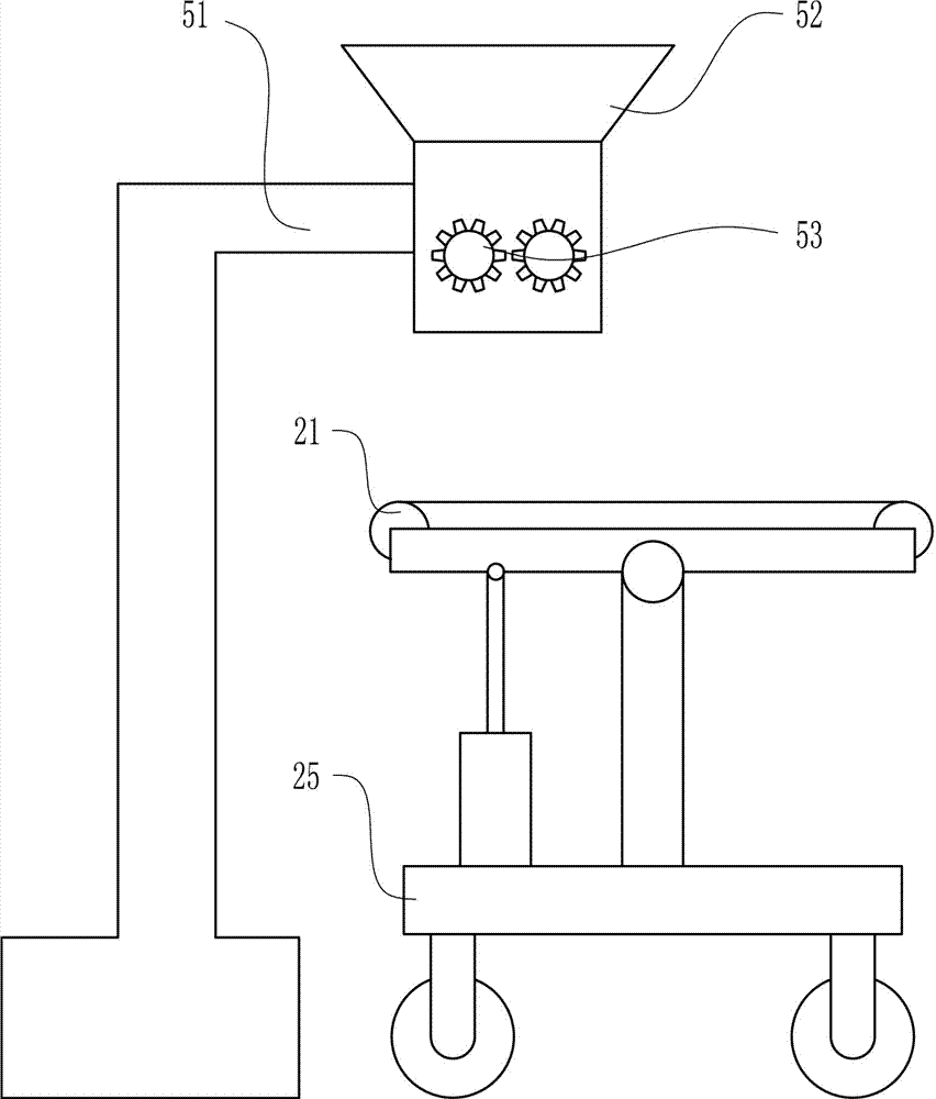
[0030] The conveying device 2 includes a belt conveyor 21, a fixed plate I22, a connecting plate 23, an upper and lower cylinder I24, a supporting plate 25 and a universal wheel 26; In the cylinder 1, a fixed p...
Embodiment 3
[0032] A horizontal pulping device for rare earth ore, such as Figure 1-3 As shown, it includes a mixing drum 1, a conveying device 2, a rotating device 3, an inlet pipe 4, an inlet valve 5, a discharge pipe 6, a discharge valve 7 and a receiving cylinder 8; There is a feed inlet, a conveying device 2 is set on the left side of the mixing drum 1, a rotating device 3 is set on the lower right of the mixing drum 1, a water inlet pipe 4 is welded on the right part of the top of the mixing drum 1, and a water inlet pipe 4 is installed on it. Water inlet valve 5, the right part of mixing drum 1 bottom is welded with discharge pipe 6, and discharge valve 7 is installed on the discharge pipe 6, and material receiving cylinder 8 is arranged on the below of discharge pipe 6.
[0033] The conveying device 2 includes a belt conveyor 21, a fixed plate I22, a connecting plate 23, an upper and lower cylinder I24, a supporting plate 25 and a universal wheel 26; In the cylinder 1, a fixed p...
PUM
 Abstract
Description
Claims
Application Information
 - R&D Engineer
- R&D Manager
- IP Professional
- Industry Leading Data Capabilities
- Powerful AI technology
- Patent DNA Extraction
Browse by: Latest US Patents, China's latest patents, Technical Efficacy Thesaurus, Application Domain, Technology Topic, Popular Technical Reports.
© 2024 PatSnap. All rights reserved.Legal|Privacy policy|Modern Slavery Act Transparency Statement|Sitemap|About US| Contact US: help@patsnap.com