
Highway tunnel very-low-frequency through-earth communication and positioning integrated system

A road tunnel, very low frequency technology, applied in positioning, radio wave measurement system, wireless communication, etc., can solve problems such as difficulty in communication network layout, construction interference, unsuitable for permanent communication base stations, etc., to reduce engineering costs and risks, improve Rescue efficiency, scientific management of engineering costs and risks

Inactive Publication Date: 2017-08-11
承德周道路桥有限公司
View PDF8 Cites 6 Cited by
  • Summary
  • Abstract
  • Description
  • Claims
  • Application Information

AI Technical Summary

Problems solved by technology

The real-time communication and ground-through positioning in the tunnel are difficult to real-time due to the complex engineering environment and the unsuitable establishment of permanent communication base stations during the construction stage.
In addition, the construction of highway tunnels involves multiple types of work at the same time, and the layout of the communication network is relatively difficult and will interfere with the construction.
At present, the personnel positioning technology also needs to arrange transmitting and receiving devices in the tunnel, and the equipment is arranged in the engineering area, and the wear and tear is serious during the tunnel excavation process.

Method used


Image

  • Highway tunnel very-low-frequency through-earth communication and positioning integrated system
  • Highway tunnel very-low-frequency through-earth communication and positioning integrated system
  • Highway tunnel very-low-frequency through-earth communication and positioning integrated system

Examples


Embodiment Construction

[0026] In order to make the technical problems, technical solutions and advantages to be solved by the present invention clearer, the following will describe in detail with reference to the drawings and specific embodiments.

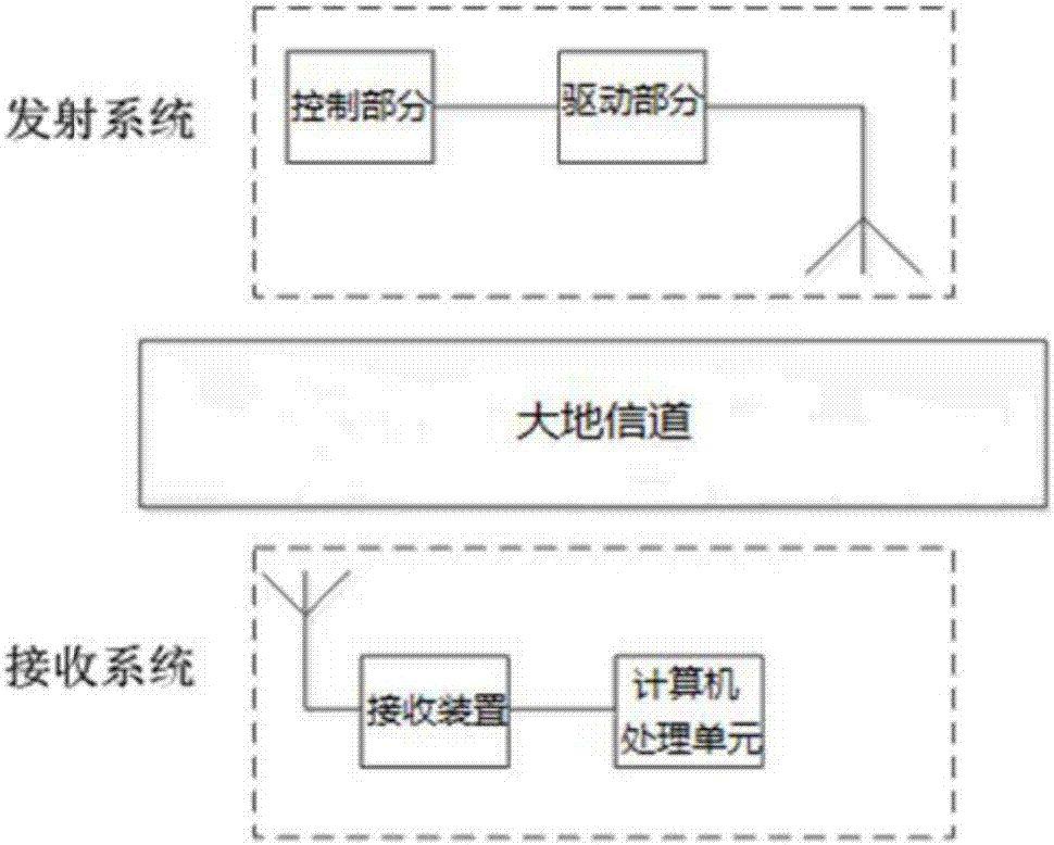
[0027] The invention provides a very low frequency ground-penetrating communication-positioning integrated system for a highway tunnel.

[0028] Such as figure 1 As shown, the system includes three parts: transmitting system, receiving system and earth communication, wherein the transmitting system includes a very low frequency electromagnetic wave transmitting antenna, a control part and a driving part, and the receiving system includes a receiving device, a filter circuit, an amplifying circuit and a computer processing unit. The control part is a very low frequency electromagnetic wave transmission control box, the driving part is a very low frequency electromagnetic wave transmission drive box, and the receiving device includes a very low frequency e...


PUM


Abstract

The invention provides a highway tunnel very-low-frequency through-earth communication and positioning integrated system, and belongs to the technical field of tunnel communication positioning. The system comprises a very-low-frequency electromagnetic wave transmission driving box, a very-low-frequency electromagnetic wave transmission control box, a very-low-frequency electromagnetic wave receiving antenna, and a cable and the like which are required for laying a coil. By connection of the cable, an optical fiber and a data line, installation of integral equipment is implemented. The receiving antenna receives a very-low-frequency electromagnetic wave in a tunnel, which is transmitted by a transmission system outside the tunnel; when electromagnetic wave communication is implemented, a receiving end is positioned; a problem that in the tunnel engineering, laying cannot be carried out or rerouting is carried out in real time along a drilling footage in the engineering construction stage in conventional wired and wireless communication methods is avoided; by laying for once, functions of real-time communication and tracking positioning of personnel inside and outside the tunnel are achieved; and when an accident occurs, contact smoothness of a landslide area and a command system can be ensured and a trapped position of personnel can be accurately positioned so as to improve rescue efficiency, thereby achieving effects of scientifically managing and reducing engineering cost and risk.

Description

technical field [0001] The invention relates to the technical field of road communication and positioning, in particular to a very low frequency through-the-ground communication-positioning integrated system for road tunnels. Background technique [0002] Due to factors such as the short construction period of highway tunnels, the cross-operation of various types of work, the mobility of construction personnel, and the efficiency of post-disaster rescue and relief, it is very important to use wireless electromagnetic wave technology to realize effective communication and positioning of personnel in the tunnel. The real-time communication and ground-through positioning in the tunnel are difficult to real-time due to the complex engineering environment and the construction stage is not suitable for the establishment of permanent communication base stations. In addition, multiple types of work are carried out at the same time in the construction of highway tunnels, and the layo...

Claims


Application Information

Patent Timeline
Patent Type & Authority Applications(China)
IPC IPC(8): H04W16/26G01S5/10
CPCG01S5/10H04W16/26
Inventor 徐国庆赵海瑜邢海东修德保颜学武
Owner 承德周道路桥有限公司
Learn More