
Underground water nitrate removal method and denitrification reactor

A groundwater and nitrate technology, applied in the direction of contaminated groundwater/leachate treatment, chemical instruments and methods, water pollutants, etc., can solve the problems of excessive pollutants and achieve the effect of improving denitrification efficiency

Active Publication Date: 2017-07-28
XI'AN UNIVERSITY OF ARCHITECTURE AND TECHNOLOGY
View PDF5 Cites 15 Cited by
  • Summary
  • Abstract
  • Description
  • Claims
  • Application Information

AI Technical Summary

Problems solved by technology

[0006] In view of the problems existing in the prior art, the object of the present invention is to provide a method for removing nitrate in groundwater and a denitrification reactor based on the method, which comprehensively utilizes hydrogen autotrophic denitrification, aerobic denitrification and electrolysis to produce hydrogen and oxygen Advantages, effectively solve groundwater NO 3 - The problem of excessive pollutants

Method used


Image

  • Underground water nitrate removal method and denitrification reactor
  • Underground water nitrate removal method and denitrification reactor
  • Underground water nitrate removal method and denitrification reactor

Examples


Embodiment 1

[0043] This embodiment provides a method for removing groundwater nitrates, comprising the following steps:

[0044] In the first step, anode electrolysis produces oxygen and CO 2 , anodic heterotrophic aerobic denitrifying bacteria preliminarily reduced nitrate in groundwater in the anode area;

[0045] In the second step, cathode electrolysis produces hydrogen, and hydrogen autotrophic denitrifying bacteria further reduce the groundwater obtained in the first step in the cathode area.

[0046] The nitrate removal rate of the groundwater entering the cathode reaction zone is over 82%.

Embodiment 2

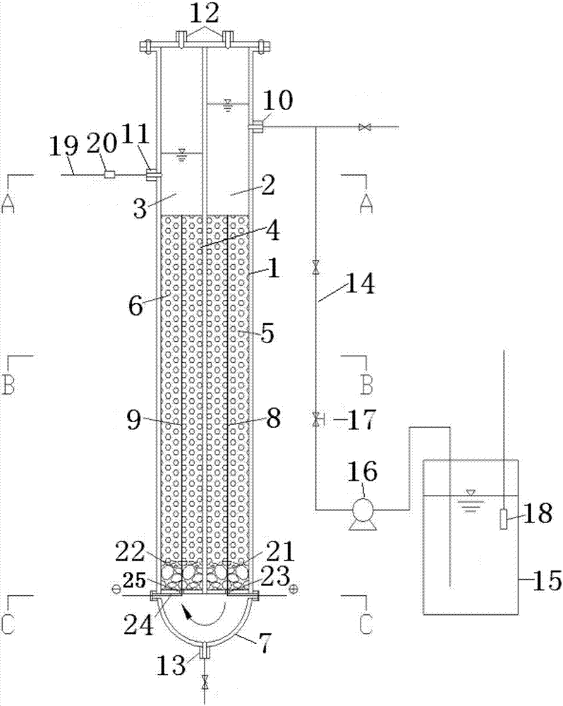
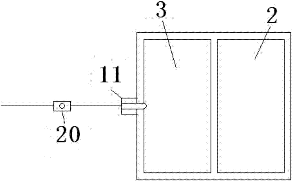
[0048] This embodiment provides a denitrification reactor, such as Figure 1-4 As shown, a housing 1 comprising a lower opening, the housing 1 is vertically provided with an anode reaction zone 2 and a cathode reaction zone 3, and the anode reaction zone 2 and the cathode reaction zone 3 are separated by a separator 4; the anode reaction zone 2 The anode filler 5 and the cathode filler 6 are respectively included in the cathode reaction zone 3, and the anode filler 5 and the cathode filler 6 are respectively attached with heterotrophic aerobic denitrifying bacteria and hydrogen autotrophic denitrifying bacteria, and the lower part of the housing 1 is connected with a semi-cylindrical Bottom cover7. The groundwater first enters the anode reaction zone 2, and the heterotrophic aerobic denitrifying bacteria use the oxygen produced by the anode electrolysis as the oxygen source to initially reduce the nitrate in the groundwater, and the reduced groundwater enters the cathode react...


PUM


Abstract

The invention discloses an underground water nitrate removal method and a denitrification reactor; electrochemistry, heterotrophic aerobic denitrification and anaerobic autotrophic denitrification are combined to construct an autotrophic-heterotrophic synergic denitrification apparatus capable of providing hydrogen and oxygen. The denitrification reactor comprises an anode reaction area and a cathode reaction area which are used for carrying out heterotrophic aerobic denitrification and anaerobic hydrogenotrophic denitrification independently; denitrifying bacteria are fixed to filler by means of film colonization; since an anode and a cathode are in contact with the filler and anode and cathode plates penetrate the filler layer, gases produced may be distributed evenly in the whole reaction area during electrolytic production of hydrogen and oxygen, and denitrification efficiency is improved. A nitrate sensor is arranged in an inflow water tank to monitor the quality of inflow water in real time, an electrolytic power supply can be controlled through feedback adjustment, the magnitude of electrolytic current is adjusted, and oxygen supply and hydrogen supply are changed accordingly. The apparatus is simple in overall structure, controllable in gas supply and convenient to operate.

Description

technical field [0001] The invention belongs to the technical field of micro-polluted water treatment, and in particular relates to a method for removing nitrate in groundwater and a denitrification reactor based on the method. Background technique [0002] The increasingly serious problem of groundwater pollution has attracted the attention of many countries around the world. In China, the common pollutant in groundwater is nitrate. In northern areas, especially in rural areas, nitrate pollution is more serious. [0003] In my country's "Drinking Water Hygienic Standards" (GB5749-2006), the nitrate nitrogen concentration standard in drinking water is 10 mg / L, the nitrite concentration standard is 1 mg / L, and the ammonia nitrogen concentration standard is 0.5 mg / L. High nitrate concentrations in groundwater can cause serious harm to human health. Nitrate can also be reduced to nitrite in the human body. Nitrite reacts with human blood to form methemoglobin, which makes th...

Claims


Application Information

Patent Timeline
IPC IPC(8): C02F3/00C02F101/16C02F103/06
CPCC02F3/005C02F2101/163C02F2103/06C02F2201/007
Inventor 苏俊峰高椿寓黄廷林高一畴郭东鑫
Owner XI'AN UNIVERSITY OF ARCHITECTURE AND TECHNOLOGY
Learn More