Valve disc multi-position plasma stellite spray welding process method
An alloy process and plasma technology, applied in the field of spray welding Stellite alloy process and welding process, can solve the problems of complex process flow, poor surfacing quality, easy cracking, etc., to achieve simple process flow, reduce production costs, avoid The effect of welding cracks
- Summary
- Abstract
- Description
- Claims
- Application Information
AI Technical Summary
Problems solved by technology
Method used
Image
Examples
Embodiment 1
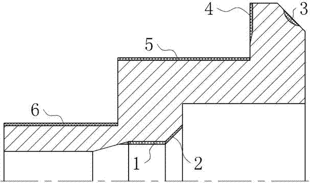
[0062] Such as figure 1 As shown, the present embodiment takes the following valve disc as an example. Among them, the size of each surface of the valve disc to be welded is: the diameter of the inner circular surface 1 is 30mm, the diameter of the small end of the inner cone surface 2 is 30mm, the cone angle is 30°, the width of the inner cone surface is 18mm, and the diameter of the outer cone surface 3 is large. The end diameter is 200mm, the taper angle is 30°, the diameter of the large end of the outer end surface 4 is 200mm, the diameter of the outer large circular surface 5 is 150mm, and the diameter of the outer small circular surface 6 is 40mm.
[0063] Such as figure 1 As shown, a multi-position plasma spray welding Stellite alloy process method of a valve disc in this embodiment includes the following steps:
[0064] Step 1. Perform plasma spray welding of Stellite alloy on the inner circular surface 1, inner conical surface 2 and outer conical surface 3 of the v...
Embodiment 2
[0086] This embodiment is basically the same as Embodiment 1, the difference is:
[0087] Such as figure 1 As shown, the present embodiment takes the following valve disc as an example. Among them, the size of each surface of the valve disc to be welded is: the diameter of the inner circular surface 1 is 50mm, the diameter of the small end of the inner cone surface 2 is 50mm, the cone angle is 45°, the width of the inner cone surface is 20mm, and the diameter of the outer cone surface 3 is large. The end diameter is 260mm, the taper angle is 45°, the diameter of the large end of the outer end surface 4 is 260mm, the diameter of the outer large circular surface 5 is 220mm, and the diameter of the outer small circular surface 6 is 70mm.
[0088] In this embodiment, in step 1,
[0089] The welding process parameters of the inner circular surface 1 are: transferred arc current 100-120A, transferred arc voltage 22V, welding speed 80mm / min, alloy powder feeding speed 18g / min, swi...
Embodiment 3
[0097] This embodiment is basically the same as Embodiment 1, the difference is:
[0098] Such as figure 1 As shown, the present embodiment takes the following valve disc as an example. Among them, the size of each surface of the valve disc to be welded is: the diameter of the inner circular surface 1 is 80mm, the diameter of the small end of the inner cone surface 2 is 80mm, the cone angle is 60°, the width of the inner cone surface is 30mm, and the diameter of the outer cone surface 3 is large. The end diameter is 400mm, the taper angle is 60°, the diameter of the large end of the outer end surface 4 is 400mm, the diameter of the outer large circular surface 5 is 350mm, and the diameter of the outer small circular surface 6 is 100mm.
[0099] In this embodiment, in step 1,
[0100] The welding process parameters of the inner circular surface 1 are: transferred arc current 120-130A, transferred arc voltage 25V, welding speed 150mm / min, alloy powder feeding speed 30g / min, s...
PUM
| Property | Measurement | Unit |
|---|---|---|
| Small end diameter | aaaaa | aaaaa |
| Large end diameter | aaaaa | aaaaa |
| Diameter | aaaaa | aaaaa |
Abstract
Description
Claims
Application Information
 - R&D
- Intellectual Property
- Life Sciences
- Materials
- Tech Scout
- Unparalleled Data Quality
- Higher Quality Content
- 60% Fewer Hallucinations
Browse by: Latest US Patents, China's latest patents, Technical Efficacy Thesaurus, Application Domain, Technology Topic, Popular Technical Reports.
© 2025 PatSnap. All rights reserved.Legal|Privacy policy|Modern Slavery Act Transparency Statement|Sitemap|About US| Contact US: help@patsnap.com

