


Quick Research
Generate reliable direction feasibility study reports for your R&D in just a few steps.

Technical Q&A
Discover and master advanced knowledge NOW. Basics, ideas, possibilities, all at once.

Find Solutions
As an expert in R&D theories, this can generate solutions to your technical problems instantly.

Evaluate Feasibility
Analyze your overall solution with one click, know your potential R&D risks in advance.

Monitor Landscape
Get weekly tech updates, stay abreast of the latest tech innovations and key insights.
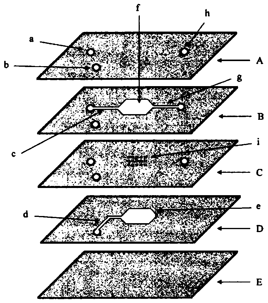
3D-printed microfluidic chip and emulsion generating device including the chip
A microfluidic chip and production device technology, applied in the field of microfluidics, can solve the problems that restrict the development and promotion of microfluidic microdroplet technology, cannot fully meet the needs of microdroplet use, and high preparation costs during the preparation process. Achieve the effects of easy concentricity, high uniformity, and reduced preparation costs
- Summary
- Abstract
- Description
- Claims
- Application Information
AI Technical Summary
Problems solved by technology
Method used
Image


Examples
example 1
[0088] In order to verify the actual effect of the emulsion generating device of this embodiment, an example of producing emulsion by using the emulsion generating device of the present invention will be introduced in detail below. The outer diameter of the PEEK tube is 1.58 mm and the inner diameter is 0.18 mm. The general commercial pipeline PTFE (Polyterfluoroethylene, polytetrafluoroethylene) tube has an outer diameter of 1.58 mm and an inner diameter of 0.75 mm. The tubing connector is a 1 / 16 inch PEEK tubing connector. The channel entering the continuous phase is a circular channel with a diameter of 1.7 mm. The side length of the section of the extended section of the dispersed phase channel is 1.7 mm. The constriction angle of the droplet generation channel is 15 degrees. The emulsion channel is a circular channel with a diameter of 1.7 mm. The continuous phase is an aqueous phase, and the dispersed phase is an oil phase, both of which are injected into the channel ...
PUM
 Abstract
Description
Claims
Application Information
 - R&D Engineer
- R&D Manager
- IP Professional
- Industry Leading Data Capabilities
- Powerful AI technology
- Patent DNA Extraction
Browse by: Latest US Patents, China's latest patents, Technical Efficacy Thesaurus, Application Domain, Technology Topic, Popular Technical Reports.
© 2024 PatSnap. All rights reserved.Legal|Privacy policy|Modern Slavery Act Transparency Statement|Sitemap|About US| Contact US: help@patsnap.com