An optical fiber vibration signal detection device and method

A technology of vibration detection and optical fiber sensing, which is applied in the direction of measuring devices, measuring ultrasonic/sonic/infrasonic waves, instruments, etc., can solve the problems of shortened detection distance, high cost of Raman amplification, and limit the maximum reflectivity of the grating to improve the response Accuracy and sensing distance, improve phase sensitivity, and reduce system cost

Inactive Publication Date: 2019-03-15
WUHAN UNIV OF TECH
View PDF5 Cites 0 Cited by
  • Summary
  • Abstract
  • Description
  • Claims
  • Application Information

AI Technical Summary

Problems solved by technology

First of all, the remote distributed optical fiber amplification system based on EDFA amplification technology is affected by nonlinear effects and modulation instability, which limits the maximum output power of EDFA, and the complex cost of the EDFA amplification system also increases to a certain extent; secondly, Raman distributed amplification The remote distributed vibration detection system of the system is affected by the double-ended light of the Raman pump light, the actual detection distance is shortened by half, and the whole amplification gain is not uniform enough, and the cost of Raman amplification is very high; again, based on the weak grating array The distributed vibration monitoring system is affected by the crosstalk between different gratings, which limits the maximum reflectivity of the grating

Method used


Image

  • An optical fiber vibration signal detection device and method
  • An optical fiber vibration signal detection device and method
  • An optical fiber vibration signal detection device and method

Examples


Embodiment Construction

[0037] The principles and features of the present invention will be further described below in conjunction with the accompanying drawings and embodiments.

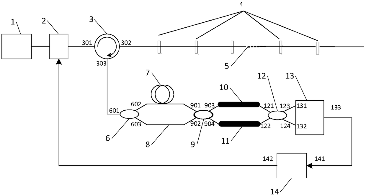
[0038] Such as figure 1As shown, the optical fiber distributed vibration detection device described in the embodiment of the present invention includes a narrowband coherent light source 1, an optical switch 2, an optical circulator 3, an optical fiber sensing array 5, a first optical fiber coupler 6, a delay optical fiber 7, Connect the optical fiber 8, the second optical fiber coupler 9, the third optical fiber coupler 12, the balance detector 13 and the data acquisition and control board 14, the narrowband coherent light source 1 is connected to the first port 301 of the optical circulator 3 through the optical switch 2; The second port 302 of the optical circulator 3 is connected to the optical fiber sensing array 5, the third port 303 of the optical fiber circulator 3 is connected to the first port 601 of the first fi...


PUM


Abstract

The invention discloses a fiber vibration signal detection device and a method. The device comprises a narrow band coherent light source, an optical switch, an optical annular device, a fiber sensing array, a first fiber coupler, a delay fiber, a connection fiber, a second fiber coupler, a first optical Kerr medium, a second optical Kerr medium, a third fiber coupler, a balancing detector and a data acquisition and control plate card. The method comprises steps of using the two optical Kerr media to carry out nonlinear phase shifting on two paths of interference light and then carry out interference; the signal acquisition and control plate card is used for controlling the optical switch to modulate narrow band light given out by the narrow band coherent light source to form pulse narrow band light; and by acquiring the output signals of the balancing detector, the size of the sensing signals is obtained. According to the invention, it is achieved that the sensing signals are amplified in case of not adopting an active amplified; phase position flexibility of the sensing signals is improved; response degree of the system is improved while complexity of a system signal processing device is reduced; and system cost is reduced.

Description

technical field [0001] The invention belongs to the technical field of optical fiber sensing, and in particular relates to an optical fiber vibration signal detection device and method. Background technique [0002] Distributed vibration detection has great application potential and broad market in practical engineering applications. At present, it is more and more widely used in large-scale structural health monitoring, power cable safety monitoring, pipeline safety monitoring, perimeter security and other fields. Distributed optical fiber vibration sensing has unique advantages compared to traditional electrical sensing systems due to its advantages such as long sensing distance and anti-electromagnetic interference. However, with the urgent need for ultra-long-distance vibration monitoring such as long-distance pipelines and national border security, it is necessary to expand the sensing distance of the distributed optical fiber vibration detection system. [0003] The ...

Claims


Application Information

Patent Timeline
Patent Type & Authority Patents(China)
IPC IPC(8): G01H9/00
CPCG01H9/004
Inventor 许儒泉
Owner WUHAN UNIV OF TECH
Why Eureka
Try Eureka