Interference structure for defense area type vibration sensing system

A technology of vibration sensing system and interference structure, which is applied in the field of optical fiber sensing and all-fiber interference, can solve the problems of high cost, insensitive system, complex structure, etc. The effect of high sensitivity

Inactive Publication Date: 2011-06-22
SHANGHAI BOOM FIBER SENSING TECH
View PDF0 Cites 2 Cited by
  • Summary
  • Abstract
  • Description
  • Claims
  • Application Information

AI Technical Summary

Problems solved by technology

Optical interference has been widely used in the field of sensing testing and communication technology, especially in perimeter security, the technology of using optical interferometry to measure vibration and stress signals is becoming more and more perfect. The existing technology uses all-fiber interferometry to measure The structure of the vibration signal system is usually relatively complicated, and the resulting high cost and system insensitivity problems have not been completely solved

Method used


Image

  • Interference structure for defense area type vibration sensing system
  • Interference structure for defense area type vibration sensing system
  • Interference structure for defense area type vibration sensing system

Examples


Embodiment 1

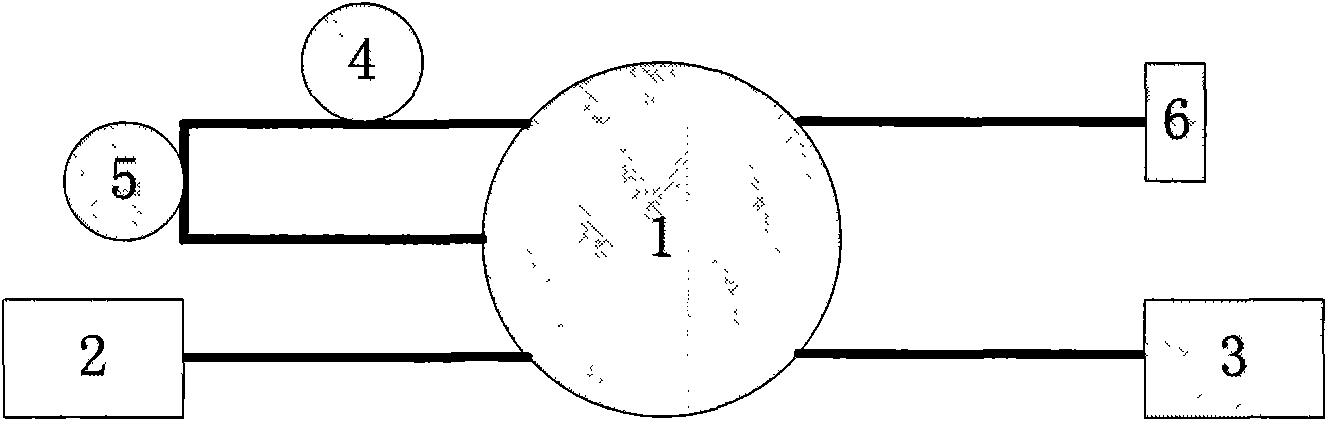
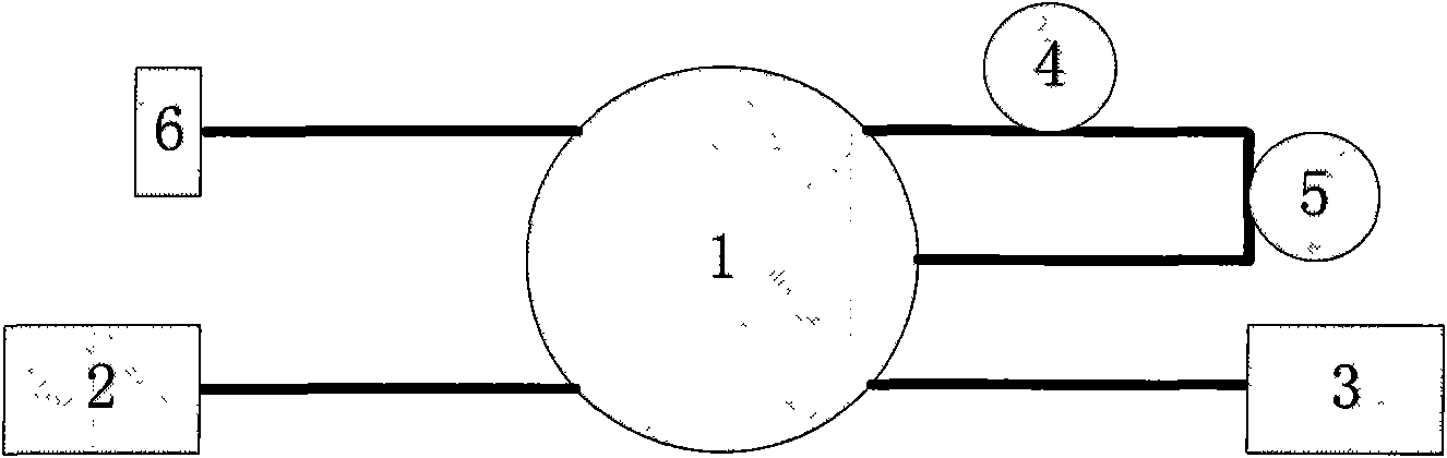
[0025] Embodiment 1: An interference structure for an anti-zone vibration sensing system, consisting of a 3×3 fiber coupler 1 , a light source 2 , a photoelectric converter 3 , a delay fiber 4 , a detection fiber 5 and a reflector 6 . The light source 2 is connected to the input end of the fiber coupler 1. After the detection fiber 5 and the delay fiber 4 are connected, the other two ends are respectively connected to the two input ends of the 3×3 fiber coupler 1, and the two ends of the 3×3 fiber coupler 1 Each output end is respectively connected to a reflection mirror 6 and a photodetector 3 through a section of optical fiber.

[0026] After the light emitted by the light source 2 is split by the 3×3 fiber coupler 1, two paths of light will interfere when returning to the photodetector. Their paths are:

[0027] (1) Light source 2-3×3 fiber coupler 1-reflector 6-delay fiber 4-detection fiber 5-3×3 fiber coupler 1-photoelectric converter 3;

[0028] (2) Light source 2-3×3 f...

Embodiment 2

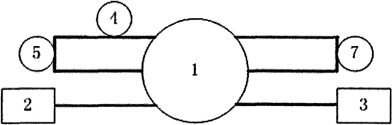
[0031] Embodiment 2: a kind of interference structure for the anti-zone type vibration sensing system, such as image 3 As shown; it consists of 3×3 fiber coupler 1, light source 2, photoelectric converter 3, delay fiber 4, detection fiber 5 and return fiber 7. One input end of the 3×3 fiber optic coupler 1 is connected to the light source 2, and a return fiber 7 is connected between the other two input ends. The two output ends of 1 are connected, and the third output end of 3×3 fiber coupler 1 is connected with a photodetector 3 .

[0032] After the light emitted by the light source 2 is split by the 3×3 fiber coupler 1, two paths of light will interfere when returning to the photodetector. Their paths are:

[0033] (3) Light source 2-3×3 fiber coupler 1-delay fiber 4-detection fiber 5-loop fiber 7-3×3 fiber coupler 1-photoelectric converter 3;

[0034] (4) Light source 2-3×3 fiber coupler 1-detection fiber 5-delay fiber 4-loop fiber 7-3×3 fiber coupler 1-photoelectric con...


PUM


Abstract

The invention discloses an interference structure for a defense area type vibration sensing system, and belongs to the technical field of optical fibers. The interference structure comprises a light source, a photoelectric detector, an optical fiber coupler, a sensing optical fiber, a detecting optical fiber and a loop device, wherein the light source and the photoelectric detector are connected with one input end of the optical fiber coupler respectively, the other input end of the optical fiber coupler is connected with one output end of the optical fiber coupler through a delay optical fiber, and the other two output ends of the optical fiber coupler are connected through the detecting optical fiber. Two beams of coherent light interfere with each other in the photoelectric detector. The system can be applied in an interference system with random phase magnitude, particularly a system with instable interference signal amplitude.

Description

technical field [0001] The invention relates to the technical field of optical fiber sensing, in particular to the technical field of all optical fiber interference. Background technique [0002] At present, as a brand-new security equipment, the all-fiber perimeter alarm system has obvious advantages. Optical interference has been widely used in the field of sensing testing and communication technology, especially in perimeter security, the technology of using optical interferometry to measure vibration and stress signals is becoming more and more perfect. The existing technology uses all-fiber interferometry to measure The structure of the vibration signal system is usually relatively complicated, and the problems of high cost and insensitivity of the system have not been completely solved. Contents of the invention [0003] In order to solve the deficiencies of the prior art, the present invention provides an interference structure for an anti-zone vibration sensing sy...

Claims


Application Information

Patent Timeline
Patent Type & Authority Applications(China)
IPC IPC(8): G01H9/00
Inventor 郭兆坤皋魏席刚仝芳轩周正仙
Owner SHANGHAI BOOM FIBER SENSING TECH
Why Eureka
Try Eureka