Full optical fiber reenterable differential interferometer
A differential interference and all-fiber technology, which is applied in the field of fiber optic sensing and all-fiber interference, can solve the problems of cost, system insensitivity, and complex structure, and achieve the elimination of reciprocity changes, high phase sensitivity, and system anti-interference ability strong effect
- Summary
- Abstract
- Description
- Claims
- Application Information
AI Technical Summary
Problems solved by technology
Method used
Image

Examples
Embodiment 1
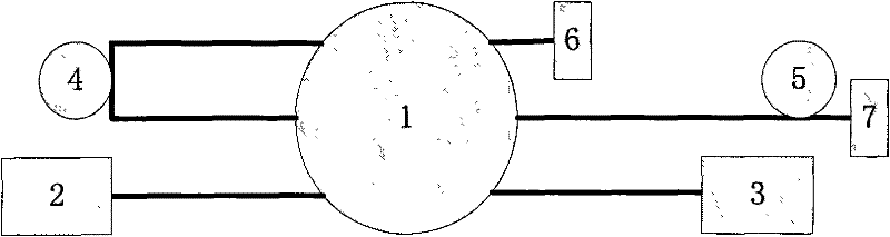
[0020] Embodiment 1: An all-fiber reentrant differential interferometer is composed of a 3×3 fiber coupler 1 , a light source 2 , a photodetector 3 , a delay fiber 4 , a detection fiber 5 and two mirrors 6 and 7 . Its structural features are as figure 1 As shown: the light source 2 and the photodetector 3 are respectively connected to an input end and an output end of the 3×3 fiber coupler 1, and the two input ends of the 3×3 fiber coupler 1 are connected through a delay fiber 4, and the 3×3 fiber coupler 1 is connected to each other through a delay fiber 4. 3. The two output ends of the fiber coupler 1 are respectively connected to a section of detection fiber 5 and a short section of fiber, and the ends of these two sections of fiber are connected to a reflection mirror 7 and a reflection device 6 respectively.
[0021] The two coherent optical paths of the present invention are:
[0022] (1) Light source 2-fiber coupler 1-detection fiber 5-mirror 7-detection fiber 5-fiber ...
Embodiment 2
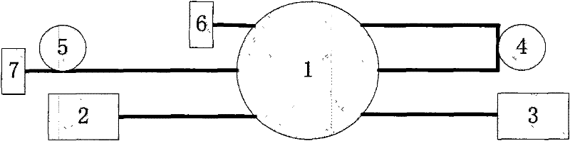
[0026] Embodiment 2: An all-fiber reentrant differential interferometer, consisting of a 3×3 fiber coupler 1, a light source 2, a photodetector 3, a delay fiber 4, a detection fiber 5, and two mirrors 6 and 7. Its structural features are as figure 2 As shown: the light source 2 and the photodetector 3 are respectively connected to an input end and an output end of the 3×3 fiber coupler 1, and the two output ends of the 3×3 fiber coupler 1 are connected through a delay fiber 4, and the 3×3 fiber coupler 1 is connected to each other through a delay fiber 4. 3 The two input ends of the fiber coupler 1 are respectively connected to a section of detection fiber 5 and a short section of fiber, and the ends of these two sections of fiber are connected to a reflection mirror 7 and a reflection device 6 respectively.
[0027] The two coherent optical paths of the present invention are:
[0028] (1) Light source 2-fiber coupler 1-delay fiber 4-fiber coupler 1-mirror 6-fiber coupler 1-...
Embodiment 3
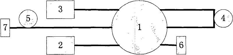
[0032] Embodiment 3: An all-fiber reentrant differential interferometer, consisting of a 3×3 fiber coupler 1, a light source 2, a photodetector 3, a delay fiber 4, a detection fiber 5, and two mirrors 6 and 7. Its structural features are as image 3 As shown: the light source 2 and the photodetector 3 are connected to the two input ends of the 3×3 fiber coupler 1, and the other input end of the 3×3 fiber coupler 1 is connected to the reflector 7 through the detection fiber 5, 3×3 The two output ends of the fiber coupler 1 are connected through a delay fiber 4 , and the other output end of the 3×3 fiber coupler 1 is connected with a reflection mirror 6 through a short length of fiber.
[0033] The two coherent optical paths of the present invention are:
[0034] (1) Light source 2-fiber coupler 1-delay fiber 4-fiber coupler 1-detection fiber 5-mirror 7-detection fiber 5-fiber coupler 1-mirror 6-fiber coupler 1-photodetector 3 ;
[0035] (2) Light source 2-fiber coupler 1-mir...
PUM
| Property | Measurement | Unit |
|---|---|---|
| Wavelength | aaaaa | aaaaa |
| Wavelength | aaaaa | aaaaa |
| Wavelength | aaaaa | aaaaa |
Abstract
Description
Claims
Application Information
 - Generate Ideas
- Intellectual Property
- Life Sciences
- Materials
- Tech Scout
- Unparalleled Data Quality
- Higher Quality Content
- 60% Fewer Hallucinations
Browse by: Latest US Patents, China's latest patents, Technical Efficacy Thesaurus, Application Domain, Technology Topic, Popular Technical Reports.
© 2025 PatSnap. All rights reserved.Legal|Privacy policy|Modern Slavery Act Transparency Statement|Sitemap|About US| Contact US: help@patsnap.com