Reflection type full optical fiber interference system

An interference system, all-fiber technology, applied in the field of all-fiber interference and optical fiber sensing, can solve the problems of complex structure, cost problem, insensitive system, etc., achieve high phase sensitivity, offset the impact of optical path asymmetry on the optical path, improve The effect of extraction ability

Inactive Publication Date: 2011-06-15
SHANGHAI BOOM FIBER SENSING TECH
View PDF0 Cites 14 Cited by
  • Summary
  • Abstract
  • Description
  • Claims
  • Application Information

AI Technical Summary

Problems solved by technology

[0002] The interference of light has been widely used in the field of sensing testing and communication technology, especially in the perimeter security, the technology of measuring vibration and stress signals by using light interferometry is becoming more and more perfect. The structure of the vibration signal system is usually relatively complicated, and the resulting cost problem and system insensitivity problem have not been completely solved

Method used


Image

  • Reflection type full optical fiber interference system
  • Reflection type full optical fiber interference system
  • Reflection type full optical fiber interference system

Examples


Embodiment 1

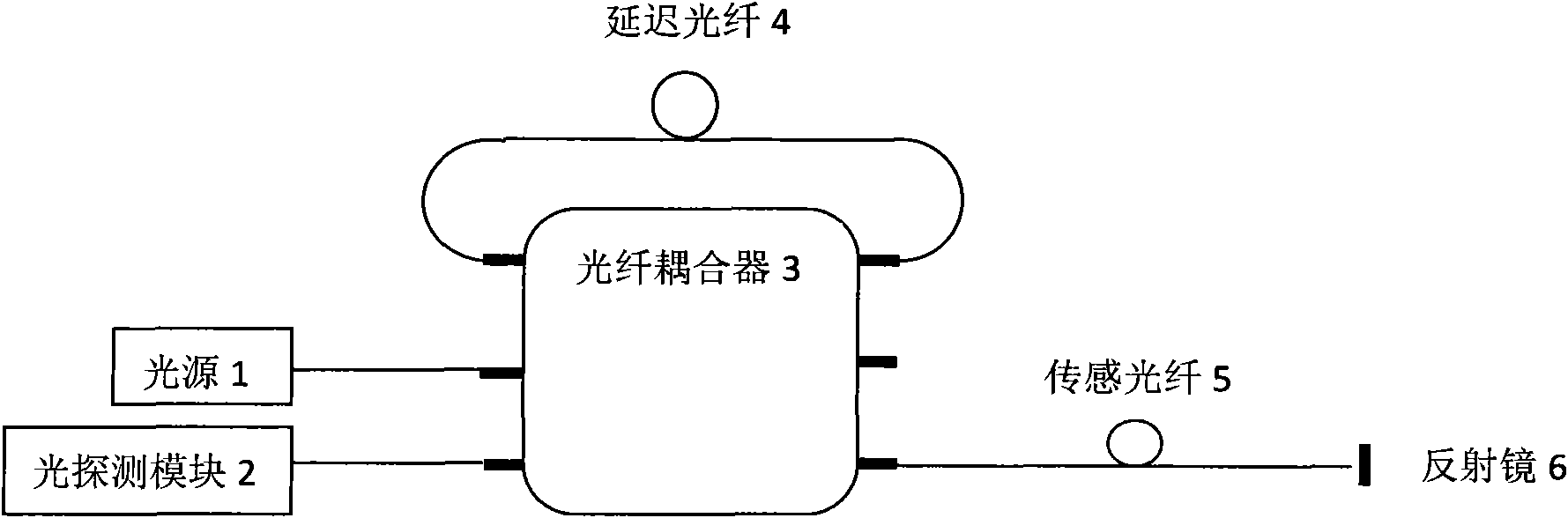
[0024] Embodiment 1: A reflective all-fiber interference system, which is composed of a light source 1 , a light detection module 2 , a 3×3 fiber coupler 3 , a delay fiber 4 , a sensing fiber 5 and a reflector 6 . Its structural features are as follows: the light source 1 and the light receiving module 2 are respectively connected to the input end of the 3×3 fiber coupler 3, and the other input end of the 3×3 fiber coupler 3 passes through the delay fiber 4 and the 3×3 fiber coupler 3 One output end is connected, one output end of the 3×3 fiber coupler 3 is connected with the sensing fiber 5 , and a reflection mirror 6 is installed at the end of the sensing fiber 5 .

[0025] The two coherent light paths in this embodiment are:

[0026] (1) Light source 1-fiber coupler 3-delay fiber 4-fiber coupler 3-sensing fiber 5-mirror 6-sensing fiber 5-fiber coupler 3-light detection module 2.

[0027] (2) Light source 1-fiber coupler 3-sensing fiber 5-mirror 6-sensing fiber 5-fiber coup...

Embodiment 2

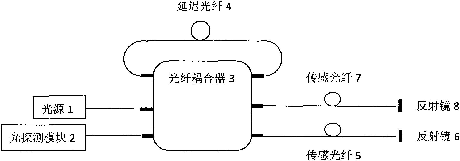
[0030] Embodiment 2: A reflective all-fiber interference system, consisting of a light source 1, a light detection module 2, a 3×3 fiber coupler 3, a delay fiber 4, a sensing fiber 5, a sensing fiber 7, a reflector 6 and a reflector 8 composition. Its structural features are as follows: the light source 1 and the light receiving module 2 are respectively connected to one input end of the 3×3 fiber coupler 3, and the other input end of the 3×3 fiber coupler 3 passes through the delay fiber 4 and the 3×3 fiber coupler 3 The other two output ends of the 3×3 fiber coupler 3 are respectively connected to the sensing fiber 5 and the sensing fiber 7, and the ends of the sensing fiber 5 and the sensing fiber 7 are equipped with a reflector 6 and a reflector 8 .

[0031] In this embodiment, two interference optical paths will be formed, and the paths are:

[0032] (1) Light source 1—optical fiber coupler 3—delay optical fiber 4—sensing optical fiber 5—mirror 6—sensing optical fiber 5...


PUM

PropertyMeasurementUnit
Wavelengthaaaaaaaaaa

Abstract

The invention discloses a reflection type full optical fiber interference system, belonging to the technical field of optical fibers. According to the system, two paths of light beams reflecting the direct current component of an output signal are obtained by using an optical fiber coupler for constructing an interference optical path, and the light beams are used for calibrating the output signal of the system to realize more precise phase detection and extraction. The system can be applied to interference systems with phases of any magnitudes, especially to the system with unstable interference to signal amplitude. The reflection type full optical fiber interference system not only can be used for sensing dynamic signals, such as velocity, pressure, strain, acoustic wave, earthquake wave and the like, in harsh and complex environments, but can also realize the functions of a optical switch, a filter and the like in an all-optical communication network, so that the system can be widely applied in the field of optical communication.

Description

technical field [0001] The invention relates to the technical field of optical fiber sensing, in particular to the technical field of all optical fiber interference. Background technique [0002] Optical interference has been widely used in the field of sensing testing and communication technology, especially in perimeter security, the technology of using optical interferometry to measure vibration and stress signals is becoming more and more perfect. The existing technology uses all-fiber interferometry to measure The structure of the vibration signal system is usually relatively complicated, and the resulting cost problem and system insensitivity problem have not been completely solved. Contents of the invention [0003] In order to solve the deficiencies of the prior art, the present invention provides a reflective all-fiber interference system. [0004] The object of the present invention is achieved as follows: a reflective all-fiber interference system is composed o...

Claims


Application Information

Patent Timeline
IPC IPC(8): G01D5/26G01D5/353G01H9/00G02B6/26
Inventor 杨斌皋魏席刚仝芳轩周正仙
Owner SHANGHAI BOOM FIBER SENSING TECH
Why Eureka
Try Eureka