Mine magnetic separator
A technology of magnetic separator and mine, applied in the direction of magnetic separation, solid separation, sieve, etc., can solve the problems of no way to achieve, the dry magnetic separator cannot meet the requirements, and the material processing capacity is large, so as to reduce the cost of magnetic separation. , Ensure safety and effectiveness, and improve the effect of equipment service life
- Summary
- Abstract
- Description
- Claims
- Application Information
AI Technical Summary
Problems solved by technology
Method used
Image
Examples
Embodiment 1
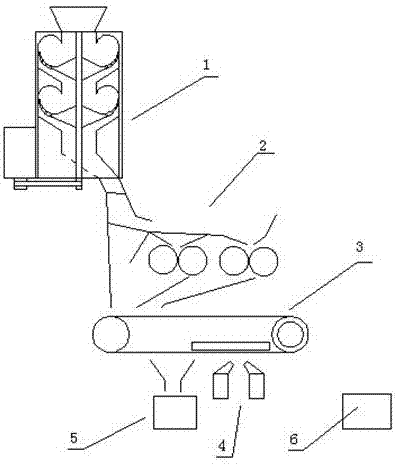
[0042] Such as figure 1 As shown, the present invention discloses a mine magnetic separator, comprising a crushing mechanism 1, a feeding mechanism 2, a conveying mechanism 7, and a magnetic separation mechanism 3; Transported into the feed mechanism 2, the output port of the feed mechanism 2 is opposite to the entrance of the magnetic separation mechanism 3.
[0043] The crushing mechanism 1 includes a hollow cylinder, and the upper and lower ends of the cylinder are respectively provided with a feed port and a discharge port. The screen part, the screen part is located outside the acceleration part; the surface of the crushing wheel cooperates with the side wall of the turning chamber to form a turning surface for magnetic ore turning; magnets are arranged in the acceleration part, and the screen part has through holes. The design of the turning chamber makes the minerals turn over, and the magnetic ore that enters first is used for turning over and then collides with the m...
Embodiment 2
[0051] A mine magnetic separation system, a crushing mechanism 1, a feeding mechanism 2, a conveying mechanism 7, a magnetic separation mechanism 3, and a controller;
[0052] The crushing mechanism 1 includes a hollow cylinder, and the upper and lower ends of the cylinder are respectively provided with a feed inlet and a discharge outlet. There are two upper and lower turning chambers in the cylinder, and the two turning chambers are respectively equipped with a disc-shaped crushing wheel. The crushing wheel It includes an acceleration part and a screen part, the screen part is located outside the acceleration part and has a through hole on the screen part; the side wall of the turning chamber has a turning part and a funnel part, and the crushing wheel is located in the middle of the funnel part, and the surface of the crushing wheel The surface of the turning part cooperates to form a turning surface for magnetic ore turning. The first output channel is formed between the cr...
Embodiment 3
[0059] Based on the magnetic separator of embodiment 1 or the magnetic separation system of embodiment 2, its magnetic separation method is:
[0060] Step 1: Put the ore particles with ore particles into the large and small crushing mechanism 1 for crushing, and the crushed ore particles fall onto the conveying mechanism 7. The conveying mechanism 7 includes a conveying belt, an equalizing frame on the conveying belt, and the upper part of the conveying belt The leveling device is arranged at intervals, and the leveling device scrapes the ore particles into the uniform material frame, and the conveyor belt quantitatively transports the ore particles to the feeding mechanism 2;
[0061] Step 2: The small ore particles fall into the magnetic separation mechanism 3 through the mesh of the screen, and the large ore particles slide down along the surface of the screen, and fall in the mesh area corresponding to the size of the ore particles, and are crushed After falling into the m...
PUM
 Abstract
Description
Claims
Application Information
 - Generate Ideas
- Intellectual Property
- Life Sciences
- Materials
- Tech Scout
- Unparalleled Data Quality
- Higher Quality Content
- 60% Fewer Hallucinations
Browse by: Latest US Patents, China's latest patents, Technical Efficacy Thesaurus, Application Domain, Technology Topic, Popular Technical Reports.
© 2025 PatSnap. All rights reserved.Legal|Privacy policy|Modern Slavery Act Transparency Statement|Sitemap|About US| Contact US: help@patsnap.com

