Cutting-free self-forming method of micro plane parts

A self-forming, planar technology, applied in the field of inertial confinement fusion research, achieves the effects of low cost, wide application range and high repeatability

Active Publication Date: 2017-06-27
LASER FUSION RES CENT CHINA ACAD OF ENG PHYSICS
View PDF3 Cites 1 Cited by
  • Summary
  • Abstract
  • Description
  • Claims
  • Application Information

AI Technical Summary

Problems solved by technology

[0004] The purpose of the invention is to solve the technical problem of secondary precision machining existing in the manufacture of tiny plane parts of inertial confinement fusion targets, and to invent a self-forming method for tiny plane parts without cutting

Method used


Image

  • Cutting-free self-forming method of micro plane parts
  • Cutting-free self-forming method of micro plane parts
  • Cutting-free self-forming method of micro plane parts

Examples


specific Embodiment approach 1

[0025] Specific Embodiment 1: This embodiment is a self-forming method without cutting of tiny planar parts, which is specifically completed according to the following steps:

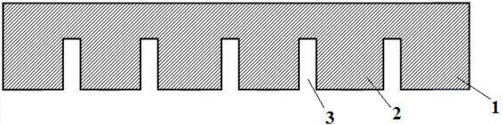
[0026] 1. Template preparation: on the Si substrate of the prefabricated pattern, a CsI release agent with a thickness of 90nm to 110nm is prepared by thermal evaporation coating technology, that is, a template plated with a release agent is obtained, and the template is stored in a vacuum or in a dry environment; the prefabricated The patterned Si substrate includes edge protrusions, graphic protrusions and grooves. The graphic protrusions are prepared according to the planar structure shape of tiny planar parts, the width of the grooves is 10 μm to 30 μm, and the width of the grooves is The aspect ratio is not less than 1, and the steepness of the groove is 90°±5°;

[0027] 2. Preparation of micro-planar part material film: adopt deposition method to prepare micro-planar part material film on the temp...

specific Embodiment approach 2

[0031] Embodiment 2: The difference between this embodiment and Embodiment 1 is that the Si substrate of the prefabricated pattern described in step 1 is prepared according to the following method: 1., substrate cleaning: adopting a thickness of 250 μm monocrystalline silicon As the substrate, and the surface roughness of the substrate is Ra<5nm, the substrate is cleaned and then dried to obtain the cleaned substrate; ②, template processing: photolithographic pattern replication and Si deep reactive ion etching In the engraving process, the substrate is processed into a template, the photoresist and chips are removed, and after cleaning, it is blown dry with nitrogen to obtain a pre-patterned Si substrate; the template includes edge protrusions, pattern protrusions and grooves, and the The graphic protrusion is prepared according to the structural shape of the tiny planar part. The width of the groove is 10 μm to 30 μm, the aspect ratio of the groove is not less than 1, the ste...

specific Embodiment approach 3

[0032] Embodiment 3: The difference between this embodiment and Embodiment 1 or 2 is that the deposition method described in step 2 is a magnetron sputtering method, a reactive magnetron sputtering method or a glow discharge plasma method; When using simple metal materials to make tiny planar parts, choose magnetron sputtering method for deposition; when using metal compounds to make tiny planar parts, choose reactive magnetron sputtering method for deposition; when using CH polymer materials to make tiny planar parts , select the glow discharge plasma method. Others are the same as those in Embodiment 1 or 2.


PUM

PropertyMeasurementUnit
widthaaaaaaaaaa
thicknessaaaaaaaaaa

Abstract

The invention discloses a cutting-free self-forming method of micro plane parts, and relates to a cutting-free self-forming preparation method of the plane micro parts (target parts) used for laser inertial confinement fusion research. The technical problem of secondary precise machining of the inertial confinement fusion target micro plane parts is solved. The method comprises the steps that firstly, an Si substrate in the prefabricated graph is used for plating a demolding agent, and a mold plate plated with the demolding agent is obtained; secondly, a deposition method is adopted to prepare a micro plane part material film on the mold plate plated with the demolding agent, and the mold plate with the micro plane part material film deposited is obtained; thirdly, demolding is carried out, wherein the micro plane part film of the mold plate surface with the micro plane part material film deposited is released, and the micro plane parts are obtained. The method has the beneficial effects that the technical problem of secondary machining of the flat micro plane size is solved, the application range is quite wide, batched production is achieved, repeated precision is high, the mold plate can be repeatedly used, the cost is low, and the method is mainly used for machining the micro plane parts.

Description

technical field [0001] The invention belongs to the research field of inertial confinement fusion, and in particular relates to a non-cutting self-forming preparation method for plane tiny zero (target) parts used in laser inertial confinement fusion experiment research. Background technique [0002] The research conditions of laser inertial confinement fusion are harsh, and experiments are usually carried out on the nanosecond time scale with picosecond resolution and the millimeter space scale with micron resolution, so that the size of the plane parts of the overall target of the fusion research physical experiment is very small: its thickness direction is thin to a hundred nanometers to a few microns, and the size in the plane direction is as small as a hundred microns to a few millimeters. In order to ensure the accuracy of physical experiment data, there are high requirements for the material purity, dimensional accuracy, and measurement accuracy of planar parts. For e...

Claims


Application Information

Patent Timeline
Patent Type & Authority Applications(China)
IPC IPC(8): C23C14/02C23C14/35C23C16/01C23C16/02C23C16/50
CPCC23C14/0005C23C14/0036C23C14/021C23C14/35C23C16/01C23C16/0245C23C16/50
Inventor 易泰民邢丕峰郑凤成杨蒙生王红莲柯博赵利平谢军李翠高莎莎李宁
Owner LASER FUSION RES CENT CHINA ACAD OF ENG PHYSICS
Why Eureka
Try Eureka