Sand mould manufacturing assembly and casting method
A technology of sand casting and sand molding, which is applied in the field of sand mold manufacturing components and casting. It can solve the problems of casting air hole defects, inability to fix cold iron, and hinder gas discharge, so as to reduce the probability of air holes, delay the chilling effect, and improve airtight performance. Effect
- Summary
- Abstract
- Description
- Claims
- Application Information
AI Technical Summary
Problems solved by technology
Method used
Image
Examples
Embodiment 1
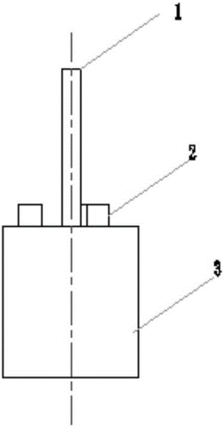
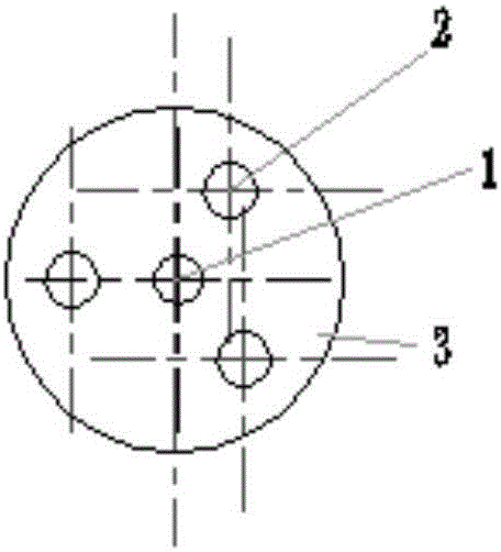
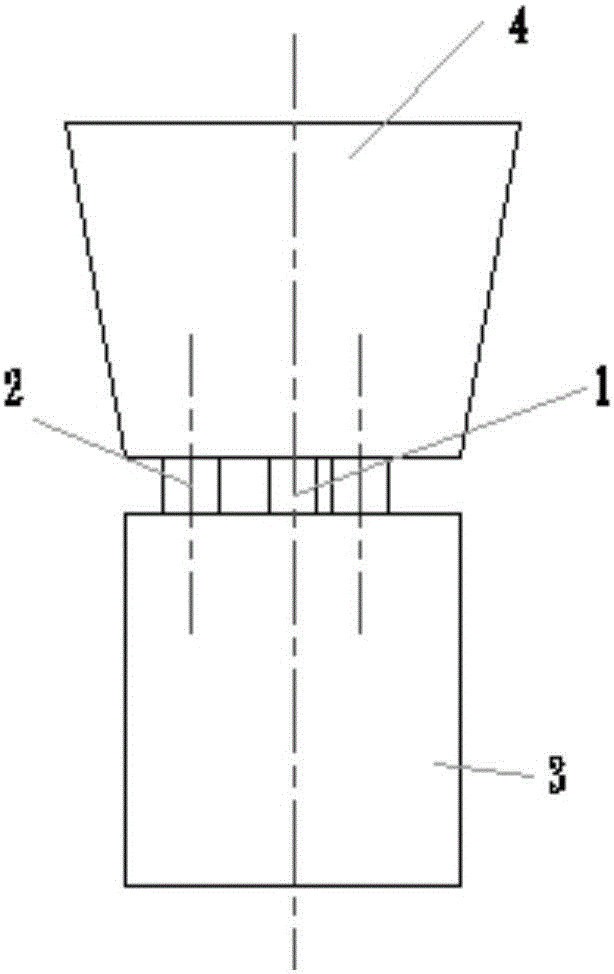
[0040] Example 1: Shrinkage defects will occur during the casting process. The so-called shrinkage porosity means that there is no liquid metal or alloy feeding in the final solidified area of the casting to form dispersed and fine shrinkage holes. The quality of forming castings, shrinkage porosity generally occurs in the axial area of the casting wall, hot joints, thick parts, riser roots and near the inner gate, and often distributed below the concentrated shrinkage holes. In the prior art, the method of designing the riser and placing the chilled iron is usually used to solve the shrinkage porosity. The riser is used to place the liquid metal supplement, and the chilled iron is used to increase the local cooling rate of the casting, so that the entire casting is close to solidification at the same time. However, in the case of using chilled iron, gas will flow upward in the casting melt. Therefore, if the chilled iron is placed above the casting, the gas cannot be melte...
Embodiment 2
[0052] Example 2: The example of the present invention provides a sand mold manufactured by using the sand mold manufacturing component in Example 1. The casting cavity made of raw sand, binders and other auxiliary materials in foundry production is called a sand mold. See Figure 5 and Image 6 , the cavity of the sand mold includes a main cavity 8 and an exhaust channel 6, the main cavity 8 is formed by the area of the mold body 3 before demolding, and the exhaust channel 6 is formed by the area of the positioning column 1 before demolding Formed, the cold iron 4 is located above the main cavity 8, the surface of the cold iron 4 opposite to the main cavity 8 is formed with a sand coating 7, and the exhaust passage 6 connects the main cavity 8 with the cold iron. The through holes of the iron 4 communicate with each other, and the exhaust channel 6 is used to discharge the gas in the sand casting process.
[0053] A hole is formed on the sand mold in the area of the su...
Embodiment 3
[0055] Embodiment 3: The embodiment of the present invention provides a casting method, and the method flow includes:
[0056] S1. Making a sand mold, the specific steps include:
[0057] S101. Preparation of molding sand.
[0058] Specifically, the preparation process of the molding sand is as follows: mixing quartz sand, hawthorn, magnesia, clay, coal powder, starch and water, and stirring evenly; then adding a binder and a hardener, mixing, and stirring evenly to obtain the ready-to-use molding sand;
[0059] S102. Fill the molding sand into the sand box, put the above components into the sand box, and then perform a compaction operation on the molding sand.
[0060] Specifically, the jarring compaction molding machine can be used to compact the molding sand in the sand box. The filled part is the main body 5 of the sand mold;
[0061] And a gate and a riser for feeding are set in the sand box. The gate is a feeding port, a narrow passage between the runner and the cavi...
PUM
| Property | Measurement | Unit |
|---|---|---|
| length | aaaaa | aaaaa |
Abstract
Description
Claims
Application Information
 - R&D Engineer
- R&D Manager
- IP Professional
- Industry Leading Data Capabilities
- Powerful AI technology
- Patent DNA Extraction
Browse by: Latest US Patents, China's latest patents, Technical Efficacy Thesaurus, Application Domain, Technology Topic, Popular Technical Reports.
© 2024 PatSnap. All rights reserved.Legal|Privacy policy|Modern Slavery Act Transparency Statement|Sitemap|About US| Contact US: help@patsnap.com


