
Carrier positioning device, material conveying device and full-automatic production line

A technology of positioning device and conveying device, applied in the direction of conveyor control device, conveyor, conveyor objects, etc., can solve the problem of inability to effectively judge the loading position of the workpiece, and achieve the effect of convenient loading and unloading, ensuring stability and improving production efficiency

Active Publication Date: 2019-01-04
SUZHOU RS TECH
View PDF6 Cites 18 Cited by
  • Summary
  • Abstract
  • Description
  • Claims
  • Application Information

AI Technical Summary

Problems solved by technology

[0005] Therefore, the technical problem to be solved by the present invention is to overcome the defect that the carrier positioning device on the automatic processing transmission line in the prior art cannot effectively judge the loading position of the workpiece, thereby providing a positioning device capable of detecting the loading state of the workpiece, material transfer Devices and fully automatic production lines

Method used


Image

  • Carrier positioning device, material conveying device and full-automatic production line
  • Carrier positioning device, material conveying device and full-automatic production line
  • Carrier positioning device, material conveying device and full-automatic production line

Examples


Embodiment 1

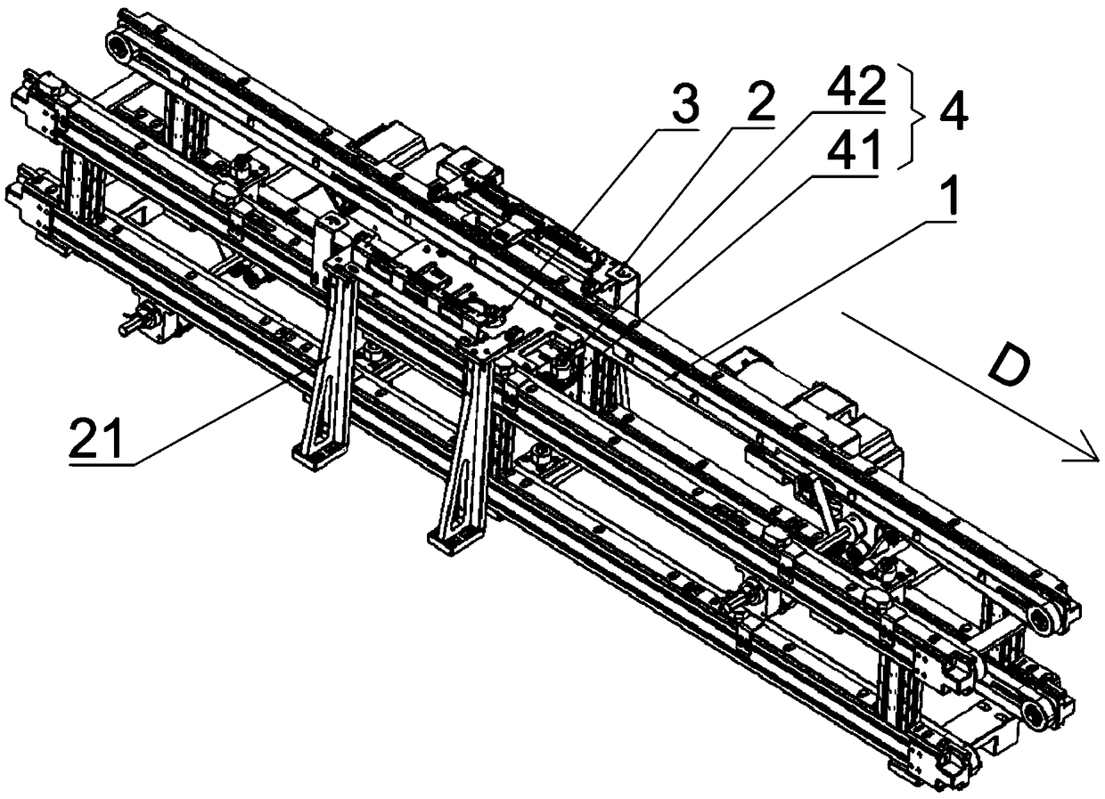
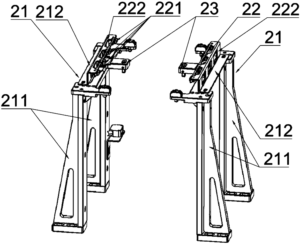
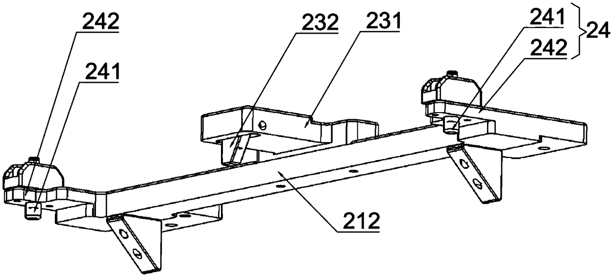
[0045] This embodiment provides a carrier positioning device, the structure of which is as follows: figure 1 As shown, it includes a jacking mechanism 3 , a blocking mechanism 4 and a positioning mechanism 2 . The jacking mechanism 3 is provided between the conveyor belts 1 that are transported in parallel. Between the conveyor belts 1, it can move up and down relative to the conveyor belt 1, and is used to lift the carrier (not shown) from the conveyor belt 1 to the working position. The positioning mechanism 2 is arranged on both sides of the conveyor belt 1 symmetrically to the conveying direction, and is used to temporarily park the carrier at the working position so that the processing equipment can operate it. The blocking mechanism 4 is arranged downstream of the jacking mechanism 3 and has a liftable blocking rod 42 , which is used to prevent the carrier from moving further.

[0046] Positioning mechanism 2 among the present embodiment is symmetrical to conveying dire...

Embodiment 2

[0056] This embodiment provides a material conveying device, which includes two conveyor belts 1 arranged in parallel, and the upper surfaces of the conveyor belts 1 are in the same horizontal plane. A drive motor is arranged beside the conveyor belt 1 to drive the conveyor belt 1 to move towards the conveying direction. On both sides of the conveyor belt 1, for example, in the area where loading or unloading is required on the conveyor belt, multiple carrier positioning devices in Embodiment 1 are provided to temporarily position the carrier so that the workpiece on the carrier can be processed or moved up and down. material.

Embodiment 3

[0058] This embodiment provides a fully automatic production line, including several stations, each station is connected with the material conveying device in Embodiment 2, and the material conveying device is provided with a carrier for transporting workpieces to each station , each station is provided with at least one carrier positioning device in Embodiment 1, so as to facilitate the operation of the processing equipment on each station.


PUM


Abstract

The invention provides a carrier positioning device which comprises a jacking mechanism and a blocking mechanism and further comprises positioning mechanisms. The jacking mechanism is arranged betweenconveying belts which conduct conveying in parallel, can move vertically relative to the conveying belts and is used for jacking a carrier to make the carrier disengaged from the conveying belts andmove to the work position. The blocking mechanism is arranged on the downstream part of the jacking mechanism in the conveying direction and is provided with a lifting blocking rod which is used for preventing the carrier from moving. The positioning mechanisms are symmetrically arranged on the two sides of the conveying belts in the conveying direction. Each positioning mechanism comprises a detecting device and a carrier unlocking device, wherein the detecting device is used for detecting the position of the carrier and the position of a workpiece in the carrier, and the carrier unlocking device is used for unlocking the workpiece in the carrier when the carrier is in the working position so as to achieve unloading of the workpiece. By means of the carrier positioning device, the position of the workpiece can be detected in the unloading process. The invention further provides a material conveying device with the carrier positioning device and a full-automatic production line.

Description

technical field [0001] The invention relates to the technical field of automatic processing, in particular to a carrier positioning loading and unloading device, a transmission line and a fully automatic production line. Background technique [0002] In the processing and production of electronic equipment, it is necessary to use the conveyor line to transport the carrier carrying the workpiece, and set up a variety of processing equipment on the conveyor line to realize automatic processing in a streamlined manner, which greatly improves production efficiency. The existing transmission lines are all straight-line structures, the span of the production line is enlarged, and the space occupied is also large. Therefore, it is necessary to realize the transportation channel of the rotary carrier, so as to realize the repeated use of the carrier and reduce the space occupied by the transmission line. . [0003] An existing circulation production line includes a frame, an upper ...

Claims


Application Information

Patent Timeline
Patent Type & Authority Applications(China)
IPC IPC(8): B65G37/02B65G47/88B65G47/22B65G43/08
CPCB65G37/02B65G43/08B65G47/22B65G47/8815B65G2203/042
Inventor 吴加富缪磊郑文坛郑俊杰冯小平
Owner SUZHOU RS TECH
Learn More