
Oil testing device and oil testing pipe column

A oil pipe and oil testing technology, which is applied in the direction of wellbore/well valve devices, drill pipes, casings, etc., and can solve problems such as high bottom hole temperature and high formation pressure

Inactive Publication Date: 2017-06-09
PETROCHINA CO LTD
View PDF4 Cites 5 Cited by
  • Summary
  • Abstract
  • Description
  • Claims
  • Application Information

AI Technical Summary

Problems solved by technology

Due to the deep burial of ultra-deep, high-temperature, and high-pressure gas reservoirs, high formation pressure, and high bottomhole temperature, there are higher requirements for the safety of oil testing in ultra-deep, high-temperature, and high-pressure gas wells. Once the blowout is out of control, it will bring great social and social harm. Economic impact

Method used


Image

  • Oil testing device and oil testing pipe column
  • Oil testing device and oil testing pipe column
  • Oil testing device and oil testing pipe column

Examples


Embodiment Construction

[0045] In order to make the purpose, technical solutions and advantages of the embodiments of the present invention clearer, the technical solutions in the embodiments of the present invention will be clearly and completely described below in conjunction with the drawings in the embodiments of the present invention. Obviously, the described embodiments It is a part of embodiments of the present invention, but not all embodiments. Based on the embodiments of the present invention, all other embodiments obtained by persons of ordinary skill in the art without creative efforts fall within the protection scope of the present invention.

[0046] The following will clearly and completely describe the technical solutions in the embodiments of the present invention with reference to the accompanying drawings in the embodiments of the present invention. Obviously, the described embodiments are only some, not all, embodiments of the present invention. Based on the embodiments of the pre...


PUM


Abstract

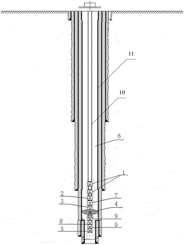
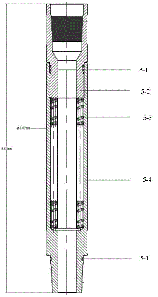
The invention provides an oil testing device and an oil testing pipe column. The oil testing device comprises an integrated pipe column which is provided with an electronic manometer holding barrel, a packer, an E valve, a second circulating valve and at least one first circulating valve from bottom to top. The electronic manometer holding barrel is used for suspension of a temperature manometer for recording well bottom temperature and pressure; the packer is in a settable structure and used for packing an oil jacket annulus between an oil pipe and a casing pipe; after setting of the packer, drilling fluid is replaced with well completion fluid trough the E valve by circulation, and then the E valve is turned off to realize isolation of the oil pipe and the casing pipe; the oil jacket annulus above the packer and a stratum below the packer are communicated by the second circulating valve through radial communication to realize unsetting of the packer; the first circulating valve realizes well bottom static temperature and static pressure measurement through radial communication and axial closure. The oil testing device has advantages that by integration of multiple functions, safety and controllability of each step in an oil test period are guaranteed, well control risks are low, and safety and high efficiency in oil testing of ultra-deep high-temperature high-pressure gas wells are realized.

Description

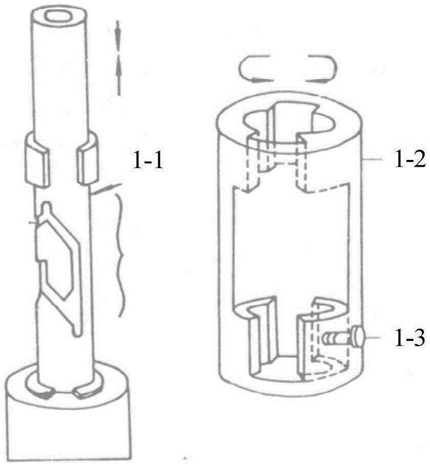
technical field [0001] The invention relates to a delivery device, in particular to an oil testing device and an oil testing string. Background technique [0002] Formation fluid samples, fluidity, productivity, formation temperature and pressure data can be obtained directly through formation testing. These data can be processed and analyzed by the analytical method or numerical simulation method of modern well test analysis to obtain formation parameters such as formation pressure, permeability, plugging ratio, skin factor, depletion, and reservoir boundary. [0003] At present, the formation tester (Multi-Flow Evaluator, referred to as MFE) is mainly used for formation oil test, and the downhole test valve switch is controlled by lifting and lowering the test string. The formation tester mainly includes a transposition mechanism, a time-delay structure and a sampling mechanism. figure 1 is a schematic diagram of the transposition mechanism of the MFE, such as figure 1 ...

Claims


Application Information

Patent Timeline
IPC IPC(8): E21B49/00E21B17/00E21B34/06
CPCE21B17/00E21B34/06E21B49/00
Inventor 周建平彭建新杨向同高文祥秦世勇张雪松
Owner PETROCHINA CO LTD
Learn More