
A terminal box suitable for on-site reconstruction of ring network cabinets

A technology of ring main unit and terminal box, which is applied in the setting of switchgear, cooling/ventilation of substation/switchgear, switchgear, etc., can solve the problems of increased contact resistance, less wifi hotspots, and uncertain opening time, etc. Achieve the effect of reducing the occurrence of arcs, ensuring data transmission, and reducing signal loss

Inactive Publication Date: 2018-08-17
LINQU POWER SUPPLY CO OF STATE GRID SHANDONG ELECTRIC POWER CO +2
View PDF5 Cites 0 Cited by
  • Summary
  • Abstract
  • Description
  • Claims
  • Application Information

AI Technical Summary

Problems solved by technology

Although this single-row terminal block saves space, it may cause poor contact surface fit during wiring, increase contact resistance, overheating, and even fire, which is defective for electrical safety. Facilitates retrofit-in-place safety
At the same time, the climate of cities along the southern coast along the river is hot and humid, and ordinary terminal blocks are prone to signal loss when they run for a long time in this environment.
[0005] The known technology is that the DTU data communication module, that is, the data transmission unit, has been widely used in the Internet of Things, but most of the currently used DTU data communication modules only use GPRS wireless mode for communication, so once there is no GPRS base station or GPRS communication module is damaged or the network When it is blocked, the data cannot be transmitted in time, which is the deficiency of the existing technology
However, there are a small number of DTU data communication modules that use wifi to communicate wirelessly. However, there are few public wifi hotspots, and the opening time of personal wifi hotspots is uncertain. Therefore, if there is no available wifi hotspot, the data cannot be transmitted in time.

Method used


Image

  • A terminal box suitable for on-site reconstruction of ring network cabinets
  • A terminal box suitable for on-site reconstruction of ring network cabinets
  • A terminal box suitable for on-site reconstruction of ring network cabinets

Examples


Embodiment 1

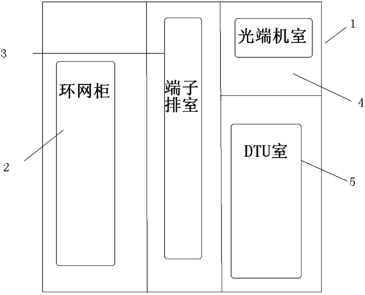
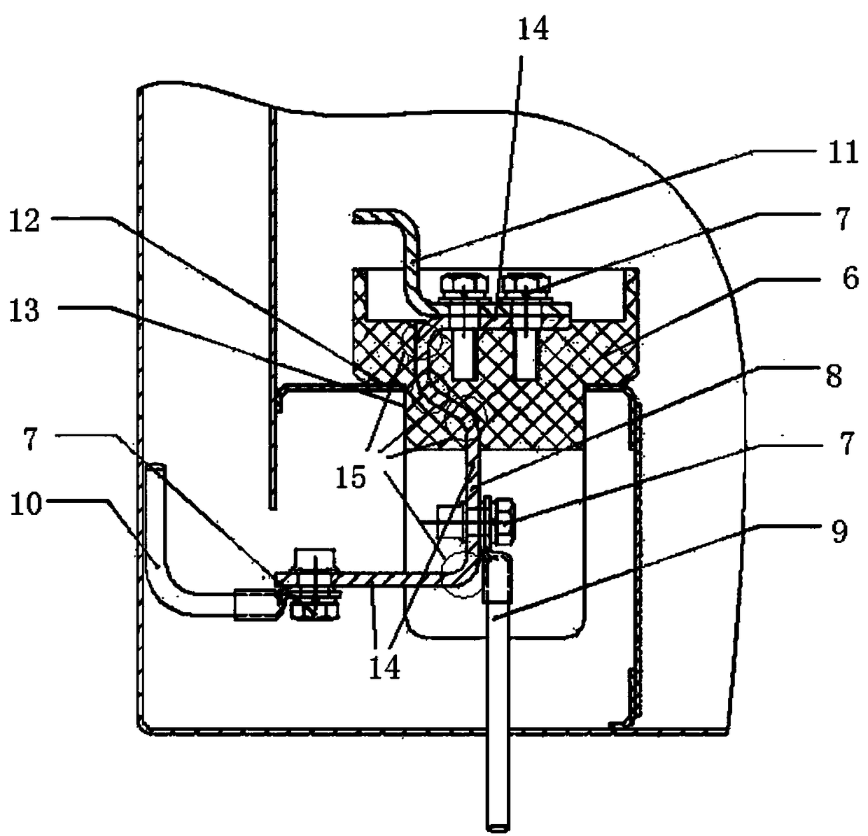
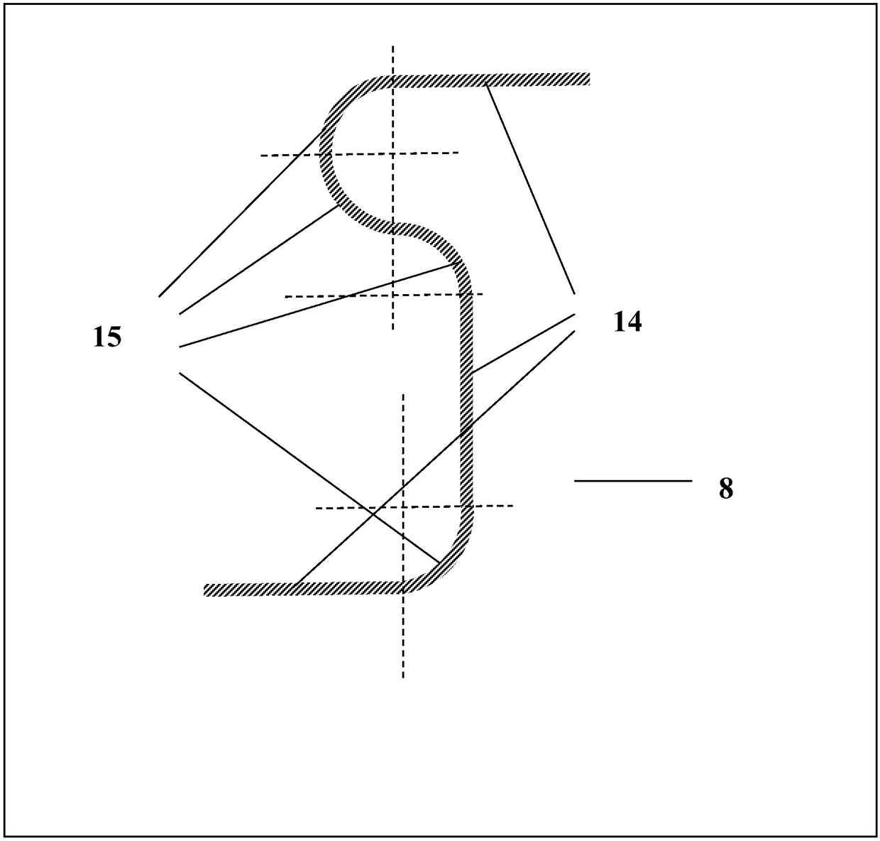
[0036] refer to figure 1 and figure 2 , the terminal box 1 suitable for on-site reconstruction of the ring network cabinet includes the ring network cabinet 2 and the side cabinet, wherein the side cabinet is composed of three parts: the terminal row room 3, the DTU room 5, and the optical terminal room 4, and the ring network cabinet 2 includes the power cabinet ( Not shown) and several switch bodies (not shown), the power supply cabinet is connected to several switch bodies to provide power supply for them, and several switch bodies complete the 2-point and closing operations of the ring network cabinet. The terminal row chamber 3 is located between the ring network cabinet 2 and the DTU chamber 5, and the terminal row chamber 3 places terminal rows (not shown), which are respectively electrically connected to a plurality of switch bodies. There is an arc-shaped connection copper bar 8 inside, one end of the arc-shaped connection copper bar 8 extends on one surface of the ...


PUM


Abstract

The invention discloses a termination box suitable for the in-situ reformation of a ring main unit. The termination box comprises the ring main unit and a side cabinet, wherein the side cabinet consists of three parts of a terminal strip chamber, a DTU (Date Transfer Unit) chamber and an optical transceiver chamber; a terminal strip is arranged in the terminal strip chamber; the terminal strip comprises a wiring terminal base plate; a circular arc type connecting copper bar is arranged in the wiring terminal base plate; the circular arc type connecting copper bar is provided with multiple rectilinear sections and multiple circular-arc sections; the radian of each circular-arc section is 90 degrees; the rectilinear sections of the circular arc type connecting copper bar are provided with bolt type wiring posts; the bolt type wiring posts and the circular arc type connecting copper bar are all coated with conducting polyaniline material; a wireless communication module comprises a CPU (Central Processing Unit) control module, a communication power supply module, a wifi (Wireless Fidelity) communication module and a GPRS (General Packet Radio Service) communication module; the wifi communication module is connected with a cloud-side server through the GPRS communication module or multiple wifi hot spots, and periodically updates a wifi account password list from the cloud-side server. By using the termination box, the in-situ reformation can be carried out on an old ring main unit; a limited space is sufficiently utilized; the fit extent of a contact surface is effectively improved; the contact resistance is decreased; the occurrence of electric arcs is decreased; the signal loss is reduced; the safety and the signal stability of a power distribution device are improved; the transmission timeliness of data is guaranteed.

Description

technical field [0001] The invention relates to the technical field of outdoor electrical equipment, in particular to a terminal box suitable for on-site reconstruction of a ring network cabinet. Background technique [0002] As the last link in the transmission and distribution of electric energy, power distribution plays a very important role in power production. Due to historical reasons, the degree of automation of power distribution equipment in the past was not high. With the development of the economy and the improvement of living standards, higher requirements are put forward for the quality and reliability of power supply. After the large-scale transformation of the two networks, the layout of the distribution network has been optimized, and the reliability of the distribution network needs to be further improved. In order to achieve a high level of distribution network automation in an all-round way, it is even more urgent to automate the transformation of old equi...

Claims


Application Information

Patent Timeline
Patent Type & Authority Patents(China)
IPC IPC(8): H02B1/46H02B1/56H02B1/28H02B13/00H02J13/00
CPCH02B1/28H02B1/46H02B1/565H02B13/00H02J13/00Y02B90/20Y04S40/126
Inventor 许朋波张圣文宋玉芳王伯林王建坤王承林刘涛孙明明冯玉婷许德龙周丽
Owner LINQU POWER SUPPLY CO OF STATE GRID SHANDONG ELECTRIC POWER CO
Learn More