A free-form catadioptric lithography projection objective lens

A technology of lithography projection and projection objective lens, which is applied in microlithography exposure equipment, optics, photography, etc., can solve the problems of not meeting high imaging performance requirements, affecting system transmittance, unfavorable mechanical adjustment, etc., and achieving excellent imaging quality , Improving lithography resolution and compact structure

Active Publication Date: 2018-02-23
BEIJING INSTITUTE OF TECHNOLOGYGY
View PDF7 Cites 0 Cited by
  • Summary
  • Abstract
  • Description
  • Claims
  • Application Information

AI Technical Summary

Problems solved by technology

[0005] The existing U.S. Patent US8643824B2 reports the design of the free-form surface deep ultraviolet lithography objective lens, which uses 6 free-form surface mirrors and 6 spherical refracting elements to make the numerical aperture of the image side reach 0.8, and the wave aberration is 80mλ. Although the components used in the system The number is small, but its numerical aperture is small, the resolution is low, and it does not meet the requirements of high imaging performance
[0006] The thirty-sixth structure of the existing US patent US7869122B2 has an image square numerical aperture of 1.2, which can meet the design requirements of high resolution, but the structure contains 25 optical elements, the total thickness of the glass material is 659mm, and the total length of the system is 1253mm , the number of components is large, which affects the transmittance of the system, and the volume is large, which is not conducive to mechanical adjustment

Method used


Image

  • A free-form catadioptric lithography projection objective lens
  • A free-form catadioptric lithography projection objective lens
  • A free-form catadioptric lithography projection objective lens

Examples


Embodiment Construction

[0038] The present invention will be further described in detail below in conjunction with the accompanying drawings.

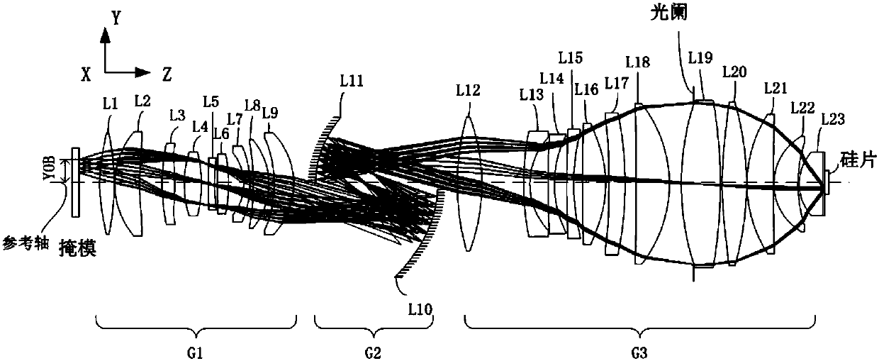
[0039] like figure 1 As shown, the free-form catadioptric lithographic projection objective lens of the present invention has no rotational symmetry axis, its object plane is the plane where the mask is located, and the image plane is the plane where the silicon wafer is located;

[0040] Including the first lens group G1, the second mirror group G2, the third lens group G3 and the aperture stop; the sequence relationship of the above-mentioned components along the incident direction of the light beam is: the first lens group G1, the second mirror group G2, the second mirror group Three-lens group G3, the aperture stop is located in the third lens group, wherein,

[0041]The first lens group G1 is a complex double-Gaussian structure with positive refractive power and a magnification range of 1.1 to 1.8. The telecentric beam emitted from the object plane is i...


PUM

PropertyMeasurementUnit
pore sizeaaaaaaaaaa
thicknessaaaaaaaaaa
refractive indexaaaaaaaaaa

Abstract

The invention provides a free-form surface turn-back type lithographic projection lens, and belongs to the technical field of high-resolution projection lithography lenses. The free-form surface turn-back type lithographic projection lens comprises a first lens group G1, a second reflector group G2 and a third lens group G3, wherein the first lens group G1 is of a double-gaussian structure, so that a mask (object plane) is imaged to a first middle image while a telecentric object space is ensured; the second reflector group G2 is of a reflecting structure, so that the first middle image is imaged to a second middle image; the third lens group G3 is a convergent lens group, so that the second middle image is imaged to a silicon wafer (image plane), high numerical aperture of an image space is achieved and 1 / 4 object image zooming ratio of a system is finally achieved. 23 optical elements are used by the system in all, wherein free-form surfaces are adopted by 4 surfaces and the numerical aperture reaches 1.2; through adjustment of various free-form surface parameters, the projection lens has excellent imaging quality and a compact structure; materials are saved, the comprehensive monochromatic wave aberration mean square root (RMS) is smaller than 0.005lamda and the full-field aberration is smaller than 1nm.

Description

technical field [0001] The invention relates to a free-form reflective lithography projection objective lens, which can be used in a scanning-stepping deep ultraviolet lithography system, and belongs to the technical field of optical design. Background technique [0002] Lithography is an integrated circuit manufacturing technology, optical lithography is the mainstream technology, and the lithography projection objective lens is the core component of the projection exposure device. The IC pattern on the mask is projected onto the rubber-coated silicon wafer through the lithography projection objective lens. [0003] Due to the continuous improvement of science and technology, various semiconductor chips are widely used in civil fields such as aerospace, military and computers, so the requirements for lithography technology are getting higher and higher. Foreign immersion lithography machines have been industrialized. Japan’s Nikon, Canon, Netherlands ASML, and Germany’s Ca...

Claims


Application Information

Patent Timeline
Patent Type & Authority Patents(China)
IPC IPC(8): G03F7/20
CPCG03F7/70275
Inventor 李艳秋毛姗姗刘岩姜家华
Owner BEIJING INSTITUTE OF TECHNOLOGYGY
Why Eureka
Try Eureka