
Groove type solar heat collector

A trough-type solar energy and heat collector technology, which is applied in the direction of solar heat collectors, solar heat collector heat insulation, and solar heat collector working fluids. , the heat dissipation of the heat collector and other problems, to achieve the effect of saving cost and space, long service life, and overcoming harsh requirements

Inactive Publication Date: 2017-05-31
SOUTHEAST UNIV
View PDF5 Cites 7 Cited by
  • Summary
  • Abstract
  • Description
  • Claims
  • Application Information

AI Technical Summary

Problems solved by technology

This structure has the following technical problems: there is a problem of welding sealing between the metal and glass, the problem of internal stress caused by the difference in expansion between the metal tube and the glass pipeline, and the problem of difficulty in ensuring the vacuum degree in the interlayer
However, the open annular tube has a hollow structure, and the inner glass is heated first, and then the heat is transferred to the outer glass by the heat-absorbing working fluid. Therefore, the internal stress of the inner and outer glass is likely to be deformed or even damaged due to the temperature difference; secondly, the set The radiator radiates more heat to the outside, resulting in more heat loss; thirdly, due to the special shape of the glass sleeve, there is no ready-made pipeline that can be directly connected to it to achieve the purpose of drawing out the heat-absorbing working fluid in the tube, which will bring To the connection problem of the end of the heat collecting tube

Method used


Image

  • Groove type solar heat collector
  • Groove type solar heat collector

Examples


Embodiment Construction

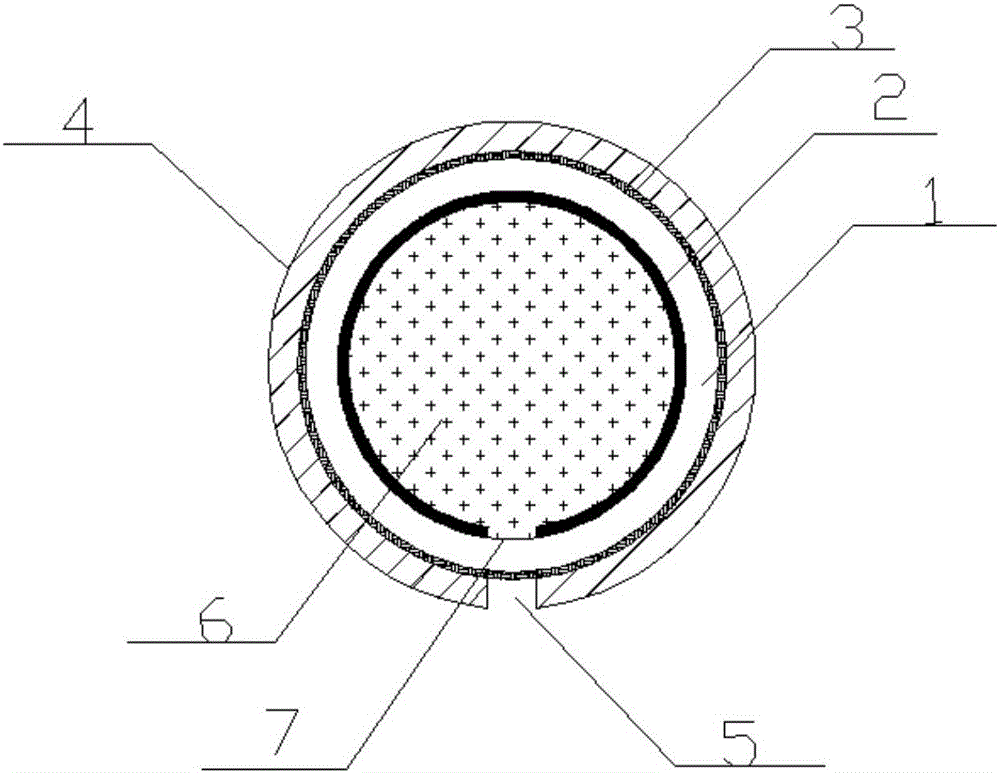
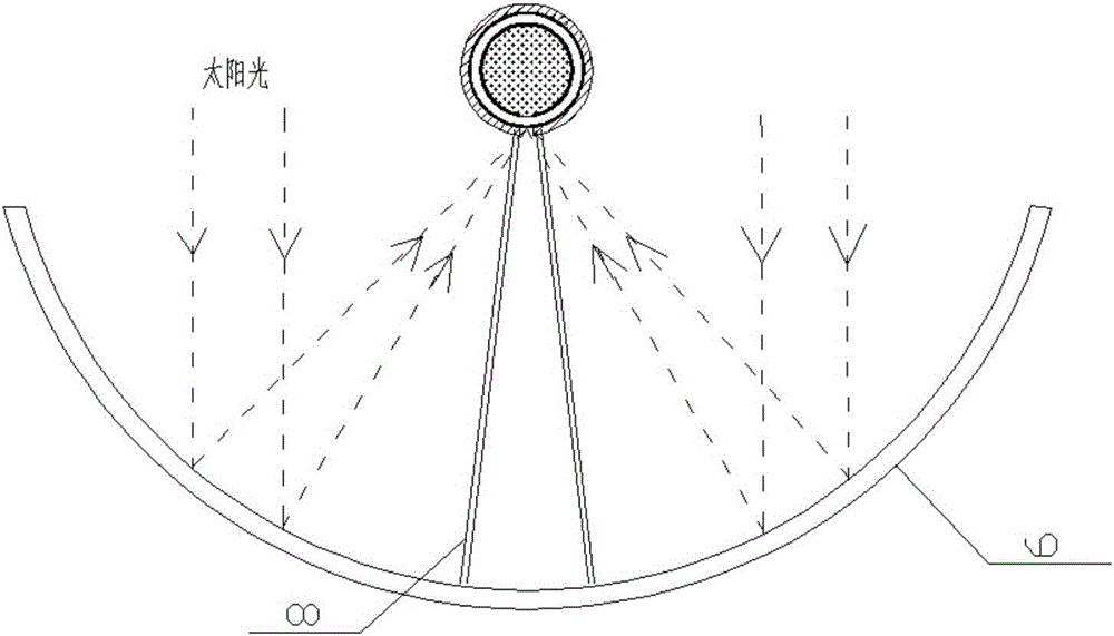
[0020] figure 1 What is shown is a schematic cross-sectional structure diagram of a heat collector of an embodiment of a trough solar heat collector disclosed in the present invention, and the heat collector includes a heat collecting tube, a concentrating paraboloid 9 and a support 7 . Wherein, the heat collecting tube includes a glass circular tube 1 , an absorbing coating 2 , a low-emissivity film 3 , an insulating layer 4 , an arc-shaped opening 5 of the insulating layer, and an arc-shaped opening 7 of the absorbing coating.

[0021] The glass tube 1 is made of high borosilicate glass with strong external impact resistance, and its linear thermal expansion coefficient is (3.3±0.1)×10-6 / K, which is a low expansion rate, high temperature resistance, high strength and high hardness. , special glass material with high light transmittance and high chemical stability. The inner surface of the glass tube 1 is attached with an absorbing coating 2, and the absorbing coating with h...


PUM


Abstract

The invention discloses a groove type solar heat collector in order to overcome the defects that traditional groove type system solar vacuum heat collecting pipes are large in machining and manufacturing difficulty, short in service life and high in manufacturing and maintenance cost. The groove type solar heat collector comprises a heat collecting pipe, a condenser and a bracket. The heat collecting pipe comprises a glass round pipe, an absorbing coating, a heat preservation layer and a heat absorbing working medium. The absorbing coating is arranged on the inner wall of the glass round pipe. The heat preservation layer is arranged on the outer wall of the glass round pipe. A heat preservation layer arc-shaped opening is formed in the heat preservation layer. An absorbing coating arc-shaped opening is formed in the position, corresponding to the heat preservation layer arc-shaped opening, of the absorbing coating. The glass round pipe is filled with the heat absorbing working medium. Furthermore, a low-radiation film is further arranged between the glass round pipe and the heat preservation layer. By means of the groove type solar heat collector of the structure, the characteristic that a blackbody cavity is high in absorption rate can be fully utilized, and the heat collecting efficiency is greatly improved; meanwhile, the defect that the requirement for vacuum of traditional vacuum pipes is rigorous can further be overcome; and the groove type solar heat collector has the advantages of being simple in structure, convenient to maintain, low in manufacturing cost and the like.

Description

technical field [0001] The invention relates to a trough-type solar collector, which belongs to the technical field of solar thermal application. Background technique [0002] The characteristics of low density, intermittent, and changing spatial distribution of solar energy also put forward high requirements for the collection and utilization of solar thermal energy. According to different types of collectors, concentrated solar thermal power generation systems can be divided into trough systems, tower systems and dish systems. Among them, the trough solar thermal power generation system has a commercial scale and relatively low technical requirements, which is an ideal power generation technology. [0003] The heat collector is an important part of the solar heat collection system. The heat collector used in the traditional trough solar heat collection system is generally a vacuum heat collection tube. The main structure of the heat collection tube is a metal tube with an...

Claims


Application Information

Patent Timeline
IPC IPC(8): F24J2/12F24J2/24F24J2/30F24J2/46F24J2/48F24J2/51F24S10/30F24S10/70F24S23/71
CPCF24S10/30F24S10/70F24S23/71F24S70/20F24S70/30F24S80/20F24S80/60F24S2080/01Y02E10/44
Inventor 周璐璐王军彼德路德丁林黄宁宁严倩雯宋鹏飞殷谦
Owner SOUTHEAST UNIV
Learn More