
Recovery system for soot in boiler waste gas

A technology for recycling system and boiler waste gas, which is applied to the separation of dispersed particles, chemical instruments and methods, combined devices, etc., can solve the problem of direct emission of waste gas to pollute the air, etc., and achieve the effect of low purification cost, avoidance of dust, and convenient cleaning.

Inactive Publication Date: 2017-05-31
南京恒誉名翔科技有限公司
View PDF0 Cites 3 Cited by
  • Summary
  • Abstract
  • Description
  • Claims
  • Application Information

AI Technical Summary

Problems solved by technology

[0003] The purpose of the present invention is to provide a smoke and dust recovery system in boiler exhaust gas, which solves the problem of direct discharge of exhaust gas to pollute the air, fully collects the smoke and dust in the exhaust gas, and effectively recycles it, avoiding the direct discharge of exhaust gas to pollute the air, The smoke and dust are fully recovered, and the recovery cost is low, the operation is simple, the resource utilization rate is improved, the environment is green, high efficiency and energy saving

Method used


Image

  • Recovery system for soot in boiler waste gas

Examples


Embodiment 1

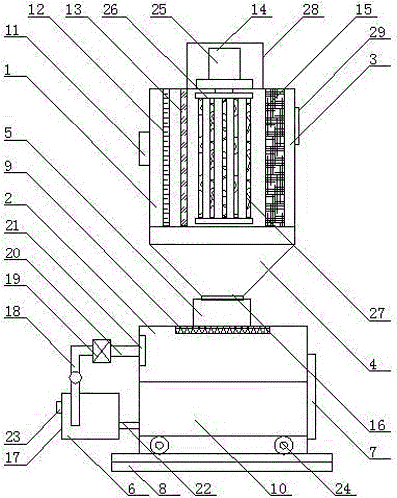
[0016] As shown in the figure, a smoke and dust recovery system in boiler exhaust gas includes a recovery system body, the upper end of the recovery system body is equipped with an electrostatic dust collection chamber 1, the lower end of the recovery system body is equipped with a smoke and dust recovery chamber 2, and the upper end of the electrostatic dust collection chamber 1 Install the dust collection bin 3, the lower end of the electrostatic dust collection chamber 1 is equipped with the ash collecting hopper 4, the bottom of the electrostatic dust collection chamber 1 is connected to the middle of the top of the dust recovery chamber 2 through the discharge pipe 5; the left side of the dust collection chamber 2 is equipped with an atomizing spray The shower device 6, the right side of the smoke recovery chamber 2 is equipped with a door 7, the bottom of the smoke recovery chamber 2 is equipped with a base 8, the top of the inside of the smoke recovery room 2 is equipped ...

Embodiment 2

[0023] Working principle: a system for recovering smoke and dust from boiler exhaust gas. The exhaust gas is passed into the electrostatic dust collection chamber 1 from the air inlet 11, filtered by the PP cotton filter 12 and the activated carbon filter 13 in turn, and then treated by the electrostatic dust collector 14. , collected by the dust collecting cloth plate 15, the purified exhaust gas is discharged through the air outlet 29, the smoke in the exhaust gas enters the ash collecting bucket 4, and enters the discharge pipe 5 from the ash outlet 16, and finally falls from the ash inlet net 9 into the dust collection box 10 at the bottom of the smoke and dust recovery chamber 2, and at the same time, the atomization spray device 6 is turned on, and the water pipe 18 quickly draws the water in the water tank 17 into the atomizer 19, and the atomized water flows from the atomization pipe 20 Enter the atomization outlet 21 and discharge through the atomization outlet 21. Whe...


PUM


Abstract

A recovery system for soot in boiler waste gas comprises a recovery system body, wherein an electrostatic dust chamber is arranged at the upper end of the recovery system body; a soot recovery chamber is arranged at the lower end of the recovery system body; a dust bin is arranged at the upper end of the electrostatic dust chamber; a dust hopper is arranged at the lower end of the electrostatic dust chamber; the bottom of the electrostatic dust chamber is connected with the middle of the top of the soot recovery chamber through a discharge pipe; an atomizing sprinkler is arranged on the left side of the soot recovery chamber; a bin door is arranged on the right side of the soot recovery chamber; a base is arranged at the bottom of the soot recovery chamber; an ash-in net is arranged at the inner top end of the soot recovery chamber; a dust box is arranged at the inner bottom end of the soot recovery chamber. The recovery system for soot in boiler waste gas fully collects and effectively recovers soot in waste gas, not only avoids air pollution caused by direct discharge of waste gas but also fully recovers soot, is low in recovery cost, simple to operate and higher in resource utilization ratio, and is environment-friendly, efficient and energy-saving.

Description

technical field [0001] The invention relates to a smoke and dust recovery system, in particular to a smoke and dust recovery system in boiler waste gas. Background technique [0002] Combustion in boilers will produce a lot of waste gas, which mainly includes harmful substances such as carbon dioxide, sulfur dioxide, carbon monoxide, dust, solid particles, etc. Direct discharge will cause serious pollution to the surrounding environment and the atmosphere. Therefore, purification of exhaust gas is of great significance for environmentally friendly thermal power generation. Most of the existing waste gas purification equipment for thermal power generation use simple filtration technology to perform multi-stage filtration treatment on the waste gas. The smoke and dust content in the exhaust gas is high, which seriously pollutes the environment. However, the waste gas and dust produced during the combustion process of thermal power generation still contains some recyclable ac...

Claims


Application Information

Patent Timeline
Patent Type & Authority Applications(China)
IPC IPC(8): B01D50/00
CPCB01D50/00
Inventor 李冰李相武王瑛费浚纯吴佳男
Owner 南京恒誉名翔科技有限公司
Learn More