
A s-band comb-line bandpass filter based on ltcc technology

A band-pass filter and comb-line technology, applied in the field of S-band comb-line band-pass filter, can solve problems such as the inability to meet the requirements of miniaturization, and achieve increased out-of-band suppression capability, shortened distance, and low insertion loss. Effect

Active Publication Date: 2019-11-19
NO 55 INST CHINA ELECTRONIC SCI & TECHNOLOGYGROUP CO LTD
View PDF3 Cites 0 Cited by
  • Summary
  • Abstract
  • Description
  • Claims
  • Application Information

AI Technical Summary

Problems solved by technology

[0003] Miniaturized filters based on LTCC technology have been frequently reported in recent years. Comb line bandpass filters are widely used in microwave frequency bands because of their compact structure. However, the principle of comb line bandpass filters is based on the resonant unit of 1 / 4-wavelength strip-shaped short-circuit line, and the 1 / 4 wavelength of the S-band is much larger than the side length of the filter, which cannot meet the requirements of system miniaturization

Method used


Image

  • A s-band comb-line bandpass filter based on ltcc technology
  • A s-band comb-line bandpass filter based on ltcc technology
  • A s-band comb-line bandpass filter based on ltcc technology

Examples


Embodiment 1

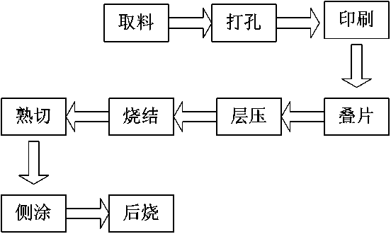
[0052] The method for making S band comb line bandpass filter comprises the following steps:

[0053] 1. Taking materials: take 21 pieces of Dupont 951C2 raw porcelain belts;

[0054] 2. Punching: punching a single piece of porcelain tape;

[0055] 3. Printing: Print metallized graphics on the front of the 5th, 10th, 11th, 12th, 13th, and 21st layer porcelain tapes and the back of the 1st layer of porcelain tapes, of which the 10th, 11th, and 12th layers 1. The metal lines in the metallized metal pattern printed on the 13th layer of the four-layer porcelain tape are arranged in a crossed manner to form the four-stage resonant unit of the filter. The pattern on the 5th layer of porcelain tape constitutes a "Z" type coupling capacitor. The metallized pattern printed on the back of the porcelain tape and the first layer of porcelain tape is the pattern that constitutes the upper and lower surfaces of the final filter;

[0056] 4. Lamination: The raw porcelain tape printed with ...


PUM


Abstract

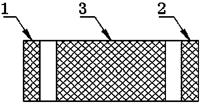
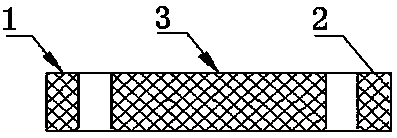
The invention is an S-band comb-shaped line bandpass filter based on LTCC technology. Its structure includes 21 layers of ceramic tapes, and the 21 layers of ceramic tapes are the first layer, the second layer, ... ..., the 21st layer; the left and right ends of the 21-layer porcelain belt have the first metallization pattern and the second metallization pattern respectively, and the middle part of the upper and lower sides of the 21-layer porcelain belt is the third metallization pattern ; The first metallization pattern and the second metallization pattern are input and output ports, and the third metallization pattern is "ground". The preparation method comprises the following steps: 1) taking material; 2) punching; 3) printing; 4) stacking; 5) laminating; 6) sintering; 7) cooked cutting; 8) side coating; 9) secondary sintering ; 10) Tin plating. Advantages: 1) It has low insertion loss in the passband, which can improve the signal-to-noise ratio; 2) It has high stop-band suppression, which can improve communication capacity and avoid interference between adjacent channels; 3) Meet the needs of system miniaturization .

Description

technical field [0001] The invention relates to an S-band comb line bandpass filter based on LTCC technology, which belongs to the technical field of wireless communication. Background technique [0002] With the continuous development of wireless communication technology, the band-pass filter, one of the most important components of the RF front-end in the wireless communication system, is being used more and more widely; a band-pass filter with excellent performance requires a low Insertion loss in the passband to improve the signal-to-noise ratio; at the same time, it is required to have a higher stopband rejection to improve the communication capacity and avoid interference between adjacent channels; in addition, the trend of system miniaturization also requires that the designed filter must Have a sufficiently small size. [0003] Miniaturized filters based on LTCC technology have been frequently reported in recent years. Comb line bandpass filters are widely used in m...

Claims


Application Information

Patent Timeline
Patent Type & Authority Patents(China)
IPC IPC(8): H01P1/20H01P1/203
CPCH01P1/20H01P1/203
Inventor 李永彬王子良
Owner NO 55 INST CHINA ELECTRONIC SCI & TECHNOLOGYGROUP CO LTD
Learn More