Inflating and igniting integrated initiator and cracking device

A detonator and integrated technology, applied in the direction of compressed gas generation, blasting barrels, weapon accessories, etc., can solve the problems of high drilling cost, low blasting power, and elimination of potential safety hazards, so as to simplify the inflatable structure and points, and realize safety The effect of blasting and avoiding potential safety hazards

Pending Publication Date: 2017-05-10
郭远军
View PDF1 Cites 2 Cited by
  • Summary
  • Abstract
  • Description
  • Claims
  • Application Information

AI Technical Summary

Problems solved by technology

[0006] The detonator with the above structure has the following problems: 1. The thermal reactants to be filled in the detonator need to be processed by mixing, mixing, coiling or bagging, and the filling process is time-consuming. 2. During the filling process of the detonator, the oxidant and reducing agent are prone to uneven mixing, resulting in low heat release efficiency; 3. The thermal reaction material needs to be mixed and filled in advance, and the temperature during transportation is too high. It is highly likely to cause combustion or explosion, and has a greater potential safety hazard; 4. Due to the delay of the detonating material or other situations, it is easy to appear the situation of squibs, and it is impossible to judge the cause of the squibs, so it cannot be eliminated by rowing the squibs Potential safety hazard; 5. The detonation method of the existing gas blaster uses a solid activator to burn to generate high temperature, which directly conducts heat to the liquid carbon dioxide, causing the liquid carbon dioxide to gasify and expand, and the heat absorption efficiency of the liquid carbon dioxide is low; 6. The heat release of the detonator The speed is slow, the chemical reaction is insufficient, the thermal release efficiency is low, the pressure of the liquid is relatively small after gasification, and the blasting power is small; 7. After the blasting, the reactants in the detonator produce a large amount of toxic and harmful gases, such as sulfur Gases such as hydrogen, sulfur dioxide, nitric oxide, and nitrogen dioxide bring relatively large poisonous pollution to the blasting site
[0008] According to the structural description of the above-mentioned existing gas blaster, it can be seen that two holes need to be opened in the plugging head with the gas charging and lead wire structure, which are respectively the filling port for filling and discharging the easily vaporized liquid and the lead wire for leading out the lead wire The problem of adopting this kind of structure is: 1. The plugging head with inflatable and lead wire structure, in the drilling process, the process is more complicated, labor-consuming and time-consuming. Larger, the sealing process is more difficult, and the problem of air leakage is prone to occur. If the hole diameter is small, the drilling will be larger and the drilling cost will be higher; 2. The lead hole needs to be filled with sealant, which is cured after sealing, and It is easy to cause deflation under high pressure; 3. High manufacturing cost

Method used


Image

  • Inflating and igniting integrated initiator and cracking device
  • Inflating and igniting integrated initiator and cracking device
  • Inflating and igniting integrated initiator and cracking device

Examples


Embodiment 1

[0069] A gas charge and ignition integrated detonator, such as figure 1 As shown, it includes a housing 1, a filling chamber 2 and an inflatable ignition head 3. The housing 1 is a filling chamber 2, and one end of the housing 1 is connected to the inflatable ignition head 3. The compressive strength of the housing 1 is greater than 5.045Mpa; The casing 1 is a carbon steel cylinder or a stainless steel cylinder, and the filling cavity 2 is filled with a reducing agent and an oxidizing agent, the oxidizing agent is liquid oxygen, supercritical oxygen or high-pressure gaseous oxygen, and the reducing agent is carbon-containing organic matter or reducing Sexuality.

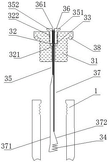
[0070] Such as figure 2 and image 3 As shown, the gas charging ignition head 3 includes a blocking base 31, an air filling hole 32, a sealing ball valve 33, a heating wire 34, a conductive joint 35 and a sealing locking screw 36, and the charging hole 32 penetrates the blocking base 31 from top to bottom, The lo...

Embodiment 2

[0080] The difference with embodiment 1 is: as Figure 4 As shown, the housing 1 includes a first segment body 11 and a second segment body 12, the first segment body 11 and the second segment body 12 are connected through a threaded structure, and are matched with a threaded sealing ring 13 for Sealing; the gas-filled ignition head 3 is respectively connected to one end of the first segment body 11 or the second segment body 11; this structure is convenient for charge.

Embodiment 3

[0082] The difference with embodiment 1 is: as Figure 5 As shown, the housing 1 is a composite layer tube containing fiber material, the housing 1 is made of composite layers, the housing 1 includes a matrix layer 101, a fiber layer 102 and a hardened layer 103, and the hardened layer 103 is located at The outer layer of the fiber layer 102, the matrix layer 101 is located in the inner layer of the fiber layer 102; the two ends of the housing 1 are respectively sealed and wrapped with a first metal joint 111 and a second metal joint 112, and the first metal joint 111 is threaded The sealed connection structure is connected to the gas-filled ignition head 3, and the second metal joint 112 is a closed head;

[0083] As a further description of the above embodiment, the base layer 101 is made of polyethylene (PE); the fiber layer 102 is made of glass fiber; the hardened layer 103 is made of epoxy resin.

[0084] As a further description of the above embodiment, the implementati...


PUM

PropertyMeasurementUnit
Compressive strengthaaaaaaaaaa
Thicknessaaaaaaaaaa
Inner diameteraaaaaaaaaa

Abstract

The invention discloses an inflating and igniting integrated initiator and a cracking device. The initiator comprises a housing, a filling cavity located in the housing and an inflating and igniting head connected at one end of the housing. Supercritical oxygen and a carbon-containing organic matter or a reductive elementary substance fill the filling cavity. The inflating and igniting head comprises a plugging base body, an inflating hole, a sealed ball valve, a conductive joint and a sealed locking screw. The inflating hole penetrates through the plugging base body from top to bottom, a sealed shrunk port is formed in the lower portion of the inflating hole, the sealed ball valve is mounted above the sealed shrunk port, the conductive joint penetrates through the sealed ball valve and is fixedly locked on the sealed ball valve, the lower spherical surface of the sealed ball valve is a non-smooth surface, an internal thread is arranged in the upper port of the inflating hole, the internal thread is in threaded connection to the sealed locking screw, a joint window for penetrating through the conductive joint is formed in the middle portion of the sealed locking screw, and the conductive joint is connected to an electric heating wire through a wire. The initiator disclosed by the invention has the advantages of being simple in filing process, good in safety, high in material mixing uniformity, low in manufacturing cost of inflating and igniting structure and good in sealing property.

Description

technical field [0001] The invention belongs to the technical field of detonators, and in particular relates to a charge-ignition integrated detonator and a cracker. Background technique [0002] Gas blasting technology is to use the vaporization and expansion of easily vaporized liquid or solid substances to generate high-pressure gas, which makes the surrounding medium expand to do work and cause fragmentation. It has the characteristics of no open flame, safety and high efficiency. [0003] Carbon dioxide gas blasters are typical blasting equipment in gas blasting technology, and are widely used in mining, geological exploration, cement, steel, electric power and other industries, subways and tunnels, municipal engineering, underwater engineering, and emergency rescue. [0004] The existing gas blaster mainly includes a vaporization liquid storage pipe and a heating detonator installed in the vaporization liquid storage pipe; the heat generation detonator ignites and gene...

Claims


Application Information

Patent Timeline
IPC IPC(8): F42B3/04F42B3/10F42B3/103F42B3/11F42B3/18C06D5/10C06B47/12C06B47/06C06B47/02C06B27/00
CPCC06B27/00C06B47/02C06B47/06C06B47/12C06D5/10F42B3/045F42B3/10F42B3/103F42B3/11F42B3/18Y02P20/54
Inventor 郭远军
Owner 郭远军
Why Eureka
Try Eureka