Spraying type loose fiber treatment device

A processing device and a technology for dispersing fibers, which are applied in the directions of processing textile material equipment configuration, spraying/jetting textile material processing, processing textile material carriers, etc., which can solve the problems of dense fiber web structure, limited fiber web thickness, and fiber web easily broken. , to achieve the effect of good processing fluency, improved processing efficiency, and improved processing efficiency

Active Publication Date: 2017-05-10
SHAOXING GUOZHOU TEXTILE NEW MATERIAL
View PDF8 Cites 3 Cited by
  • Summary
  • Abstract
  • Description
  • Claims
  • Application Information

AI Technical Summary

Problems solved by technology

[0002] Bulk fibers are usually dyed by dyeing vats. The bulk fibers to be dyed are put into dyeing cages, hung into the dyeing vats, and the temperature and time are controlled for dyeing treatment. The cleaning process needs to consume a lot of water, cleaning agent, etc., and the cleaning cost is relatively high; while the conventional water washing machine is mainly composed of a bathing pool and several pairs of upper and lower rollers arranged up and down, and the lower roller is located in the bathing pool. In the lotion, based on the structure of the washing machine, only the fabric or cloth can be washed, and the loose fiber is in a discontinuous state, so it cannot be washed with the existing washing machine. The dyed loose fiber can only be woven into fabric or After forming the net, the overall washing needs to go through multiple washings, the washing effect is not good, the water consumption is huge, and depending on the dye, hot water washing, alkali washing, soaping or even acid washing are required, and the washing cost is high
[0003] In view of the above-mentioned defects, there are also pouring-type water washing and pouring-type dyeing that adopt horizontal conveying, that is, the loose fibers are placed between the upper and lower nets, and the dyeing or washing of the loose fibers is realized through the extrusion of the two nets. Although this method overcomes the above-mentioned defects, in the process of processing, the driving roller speeds of the upper and lower nets are inconsistent, and the fiber web is easily broken; between the upper and lower nets, the fibers are subjected to a large extrusion force, resulting in a dense fiber web structure, which is difficult to clean. Or the dyeing cannot be completely completed; at the same time, because the dyeing or cleaning of the fiber is completed under the squeeze between the upper and lower nets, the thickness of the fiber web is limited, and the amount of fiber that can be processed is also limited

Method used


Image

  • Spraying type loose fiber treatment device
  • Spraying type loose fiber treatment device
  • Spraying type loose fiber treatment device

Examples


Embodiment 1

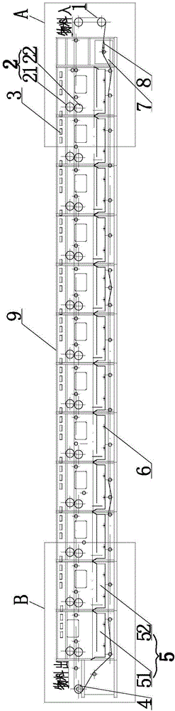
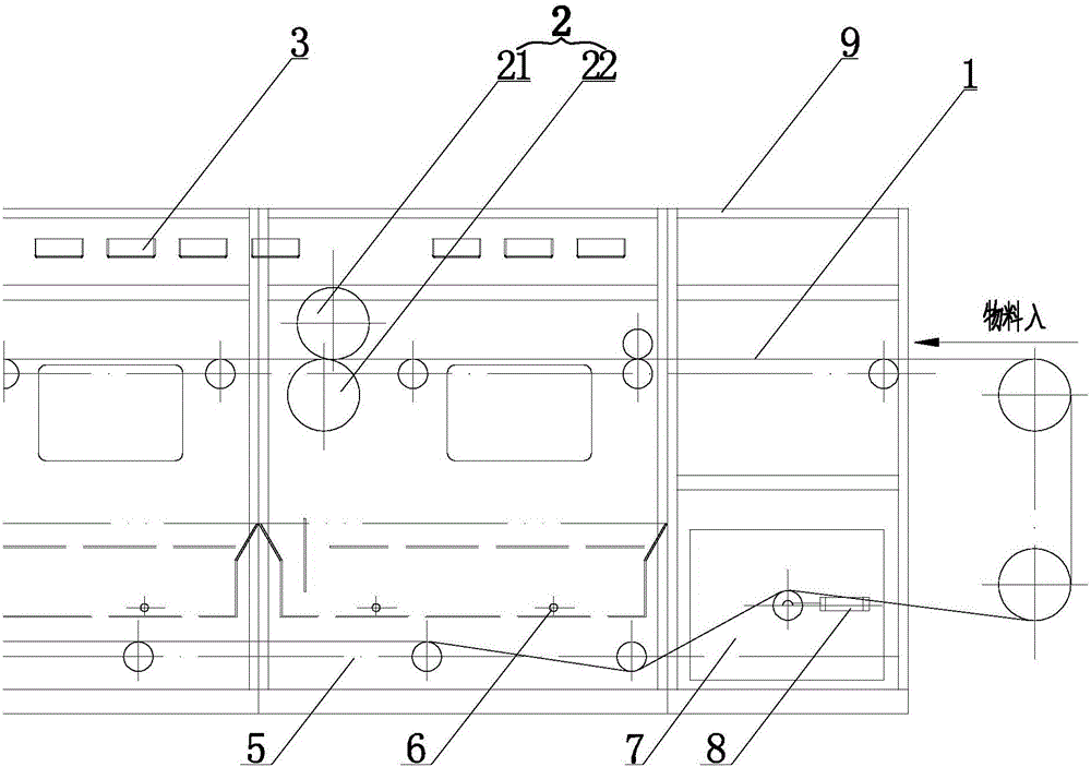
[0026] In this embodiment, a spray type bulk fiber processing device is combined with figure 1 , figure 2 and image 3 , the loose fibers to be processed are placed on the processing net 1, and the processing net 1 rotates under the drive of the driving roll 4, and several groups of rolls 2 are arranged along the advancing direction of the processing net 1, and the rolls 2 include an upper roll 21 and a lower roll 22, and the upper roll 2 The roll 21 and the lower roll 22 are separated above and below the processing net 1, the central axis of the upper roll 21 is misaligned with the central axis of the lower roll 22, and the central axis of the upper roll 21 passes through the lower roll 22, and the upper roll 21 and the lower roll 22 The direction of rotation is opposite, so as to drag the loose fibers to advance with the treatment net 1; the treatment liquid is sprayed down from the treatment tank 3 above the upper roll 21, and the loose fibers on the treatment net 1 are d...

Embodiment 2

[0034]The setting and working principle of this embodiment are the same as that of Embodiment 1, the difference is that: a processing liquid tank 5 is arranged under the processing network 1 for receiving and supplying the processing liquid to the processing tank 3; a heating pipe 6 is arranged in the processing liquid tank 5 to treat A water tank 7 is arranged below the net 1 for supplying clear water and adjusting the concentration of the treatment liquid; a heat exchanger 8 is arranged in the water tank 7 for stabilizing the temperature of the clear water and the treatment liquid and for stabilizing the temperature of the treatment liquid.

[0035] The treatment liquid enters from the treatment liquid tank in the last area 51 (that is, along the direction of the treatment network, near the outlet of the box body), and is pumped into the treatment tank 3. After overflowing, the fiber material is processed, and the treatment liquid returns to this tank. In the next treatment l...

Embodiment 3

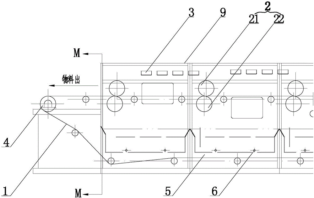
[0037] The setting and working principle of this embodiment are the same as that of Embodiment 1, the difference lies in: combining Figure 4 , at the position near the exit of the box body 9, fixing seats 92 are respectively fixed on the opposite side wall plates 91 of the box body 9, and an upper pressing plate 93 and a lower supporting plate 94 are installed on the fixing seats 92, and the processing net 1 is fixed on the opposite side. Between the two fixed seats 92, the upper pressing plate 93 is inclined downward, and a baffle plate 95 is arranged towards one end of the processing net 1, the baffle plate 95 can be set as an elastic rubber plate, and the lower supporting plate 94 is positioned under the processing net 1, The fixing seat can be fixed together with the upper pressing plate 93 , and the processing net 1 can be fixed together with the upper pressing plate 93 . The processed fiber is scraped off through the baffle plate 95 to prevent it from being taken out by...


PUM


Abstract

The invention relates to a spraying type loose fiber treatment device, belonging to the technical field of loose fiber treatment. The spraying type loose fiber treatment device comprises a box body, a treatment net, rollers and a spraying mechanism located in the box body, wherein four edges of the box body are sealed and an inlet and an outlet are formed in front and rear ends of the box body; the treatment net is driven by a driving roller and enters from the inlet and exits from the outlet; a plurality of groups of rollers are arranged along the movement direction of the treatment net; the rollers comprise upper rollers and lower rollers, and the upper rollers and the lower rollers are located above and below the treatment net respectively; the middle axis of each upper roller is staggered from the middle axis of each lower roller; the middle axis of each upper roller penetrates through the corresponding lower roller, and rotary directions of the upper rollers and the lower rollers are opposite; and a treatment solution in the spraying mechanism is sprayed downwards from the upper side of the treatment net. The spraying type loose fiber treatment device provided by the invention is applied to procedures of dyeing, color fixation, washing, softening and the like of loose fibers and has the advantages of low energy consumption, great treatment amount, good treatment effect and the like.

Description

technical field [0001] The invention relates to a spray type bulk fiber processing device, which belongs to the technical field of bulk fiber processing. Background technique [0002] Bulk fibers are usually dyed by dyeing vats. The bulk fibers to be dyed are put into dyeing cages, hung into the dyeing vats, and the temperature and time are controlled for dyeing treatment. The cleaning process needs to consume a lot of water, cleaning agent, etc., and the cleaning cost is relatively high; while the conventional water washing machine is mainly composed of a bathing pool and several pairs of upper and lower rollers arranged up and down, and the lower roller is located in the bathing pool. In the lotion, based on the structure of the washing machine, only the fabric or cloth can be washed, and the loose fiber is in a discontinuous state, so it cannot be washed with the existing washing machine. The dyed loose fiber can only be woven into fabric or After forming the net, the ov...

Claims


Application Information

Patent Timeline
Patent Type & Authority Applications(China)
IPC IPC(8): D06B1/02D06B23/18D06B23/04D06B23/20
Inventor 金国周俞月根王如洪陶华冠
Owner SHAOXING GUOZHOU TEXTILE NEW MATERIAL
Why Eureka
Try Eureka