Multilayer material layered milling machining system and method based on space combination laser focal point
A technology of spatial combination and multi-layer materials, applied in metal processing, laser welding equipment, metal processing equipment, etc., can solve problems such as inefficiency, and achieve the effect of high-efficiency, high-precision, high-quality laser drilling
- Summary
- Abstract
- Description
- Claims
- Application Information
AI Technical Summary
Problems solved by technology
Method used
Image
Examples
Embodiment 1
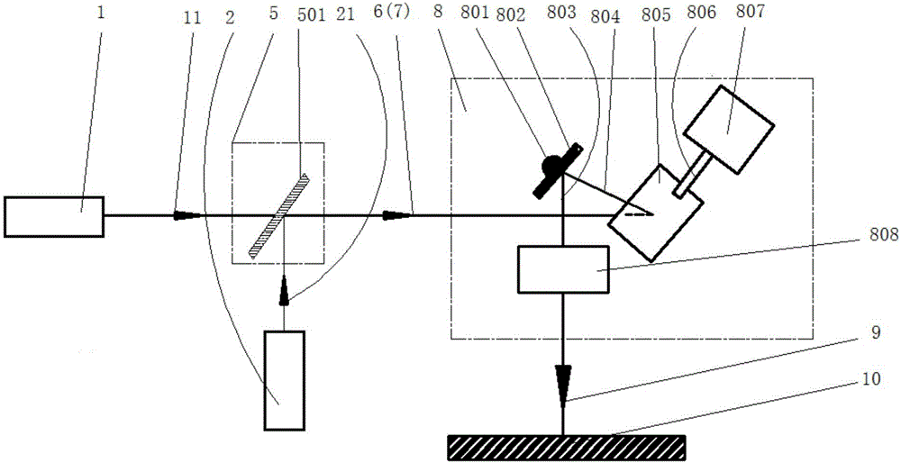
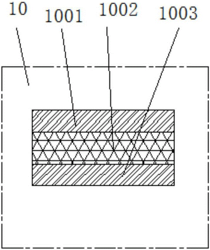
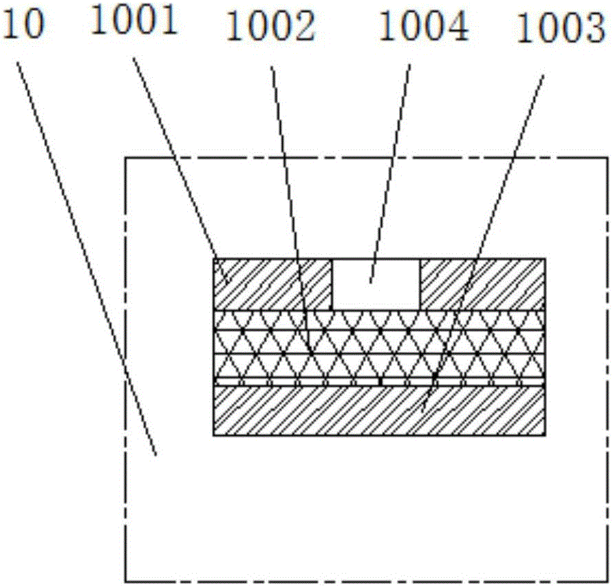
[0079] Embodiment 1. A multi-layer material layered milling and drilling system based on spatially combined laser focus. Combine below Figure 1-Figure 3 The system provided in this embodiment will be described in detail.
[0080] see figure 1 , the multi-layer material layered milling and drilling system based on spatially combined laser focus provided in this embodiment includes a window milling laser 1, a selective milling laser 2, a laser beam combiner 5, and a laser focusing and focus switching module 8;
[0081] The window milling laser 1 is used to generate the first window milling laser beam 11, and enter the laser beam combiner 5;
[0082] The selected milling laser 2 is used to generate a first selected milling laser beam 21, and enter the laser beam combiner 5;
[0083] The laser beam combiner 5 is used to combine the incident first window milling laser beam 11 and the first selected milling laser beam 21, and output the second window milling laser beam 6 and Th...
Embodiment 2
[0101] It can be seen from the above-mentioned embodiment 1 that the focal point of the window-opening milling laser and the focal point of the selected milling laser constitute a spatially combined laser focal point (not marked in the figure). On the basis of the above-mentioned embodiment 1, the focal point of the selected milling laser can be selected in this embodiment. It is further designed to distribute the laser focus with a flat top. please see Figure 4 , the beam shaper 3 is set between the selected milling laser 2 and the laser beam combiner 5, so that the corresponding selected milling laser focus transverse field strength distribution is a flat-top spot distribution. The advantage of this design is that the flat-top laser is very conducive to high efficiency The high-quality milling process makes the bottom of the blind hole clean and the cleaning efficiency is extremely high.
[0102] In addition, in this embodiment, a laser fine modulation motion module 2 can ...
Embodiment 3
[0112] Embodiment 3. A layered milling method for multi-layer materials based on spatially combined laser focus.
[0113] see Figure 5 , the method provided in this embodiment specifically includes:
[0114] S1, the first window milling laser beam generated by the window milling laser and the first selected milling laser beam generated by the selective milling laser enter the laser beam combiner respectively;
[0115] S2, the laser beam combiner combines the first window milling laser beam and the first selected milling laser beam, outputs the second window milling laser beam and the second selected milling laser beam transmitted in parallel in the same direction, and incident Laser focusing and focus switching module;
[0116] S3, the laser focusing and focus switching module focuses the second windowing milling laser beam and the second selected milling laser beam traveling in parallel in the same direction to obtain a spatially combined laser focusing focus, and controls...
PUM
| Property | Measurement | Unit |
|---|---|---|
| thickness | aaaaa | aaaaa |
| diameter | aaaaa | aaaaa |
| diameter | aaaaa | aaaaa |
Abstract
Description
Claims
Application Information
 - R&D
- Intellectual Property
- Life Sciences
- Materials
- Tech Scout
- Unparalleled Data Quality
- Higher Quality Content
- 60% Fewer Hallucinations
Browse by: Latest US Patents, China's latest patents, Technical Efficacy Thesaurus, Application Domain, Technology Topic, Popular Technical Reports.
© 2025 PatSnap. All rights reserved.Legal|Privacy policy|Modern Slavery Act Transparency Statement|Sitemap|About US| Contact US: help@patsnap.com


