Eureka AIR delivers breakthrough ideas for toughest innovation challenges, trusted by R&D personnel around the world.

Fuse wire filled multifunctional controllable additive manufacturing device

A kind of additive manufacturing and multi-component technology, which is applied in the direction of manufacturing tools, electron beam welding equipment, metal processing equipment, etc., can solve the problems of unstable vacuum degree of vacuum chamber, increased manufacturing cost of vacuum chamber, and reduced protection safety factor. Achieve the effects of fast welding and cooling speed, improved fusion ratio, and small welding heat-affected zone

Inactive Publication Date: 2017-05-10
NANJING UNIV OF SCI & TECH
View PDF7 Cites 21 Cited by
  • Summary
  • Abstract
  • Description
  • Claims
  • Application Information

AI Technical Summary

Problems solved by technology

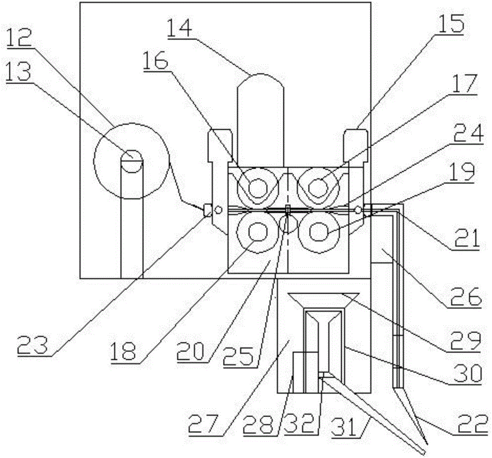
[0006] The present invention is aimed at the disadvantages of needing to re-add vacuum chambers in the prior art and can only carry out electron beam additive manufacturing by wire feeding or powder feeding, and designs a built-in electron beam fuse filling multi-component controllable The purpose of the additive manufacturing processing device is to solve the problem that in the existing device, the fuse filling mechanism and the workpiece are located in different vacuum chambers, resulting in an increase in the manufacturing cost of the vacuum chamber, a decrease in the protection safety factor of the equipment, and the vacuum degree of the vacuum chamber during welding. Stable shortcomings, and at the same time, it can realize welding by filling methods such as wire filling and particle filling, and realize efficient preparation of functionally graded materials

Method used


Image

  • Fuse wire filled multifunctional controllable additive manufacturing device
  • Fuse wire filled multifunctional controllable additive manufacturing device
  • Fuse wire filled multifunctional controllable additive manufacturing device

Examples


Embodiment 1

[0032] Embodiment 1, select non-melting slag filling welding with particles, the specific implementation steps are as follows:

[0033] 1. Turn on the high-voltage power supply 6, start the vacuum preheating for 45 minutes, and fix the substrate required for additive manufacturing on the workbench;

[0034] 2. Place the metal particles required for filling in the material storage box 29, adjust the size of the valve 32 according to the size of the weld, and use the valve 32 to control the flow of the metal particles.

[0035] 3. Adjust the outlet of the material guide pipe 31 to the weld seam through the adjustment of the motor 28, so that the metal particles are pre-filled.

[0036] 4. Close the vacuum chamber, and the vacuum chamber is evacuated by the vacuum unit. When the vacuum of the gun and the vacuum of the chamber reach 7E-2 and 8E-3 respectively, turn on the intermediate frequency unit, parameter power supply, high voltage and filament current, and the electron gun 3...

Embodiment 2

[0040] Embodiment 2, select non-melting slag inclusions of particles and wire filling welding, the specific implementation steps are as follows:

[0041] 1. Turn on the high-voltage power supply 6, start the vacuum preheating for 45 minutes, and fix the substrate learned by additive manufacturing on the workbench;

[0042] 2. Wrap the n kinds of wire materials required for additive manufacturing on the corresponding welding wire spools 12, respectively install them on the corresponding welding wire spool shafts 13, and pass the welding wire through the wire guide nozzle and the concave hole on the active wire feeding wheel. Groove, connecting rod mechanism, groove on the driven wire feed wheel, enter the wire feed hose, turn on the control switch of the wire feeder, pass the metal wire through the wire feed hose, the four-dimensional adjustment machine, and pass through the wire guide nozzle . Adjust the protruding length of the two wires. The metal particles required for fi...

Embodiment 3

[0048] Embodiment 3, the same kind of wire material is selected to be fed at the same speed for multi-wire additive manufacturing, and the specific implementation steps are as follows:

[0049] Turn on the high-voltage power supply 6, start the vacuum preheating for 45 minutes, and fix the substrate learned by additive manufacturing on the workbench;

[0050] The same kind of wire required for additive manufacturing is wound on the wire spool 12, and installed on the wire spool shaft 13 respectively, and the welding wire is passed through the wire guide nozzle, the groove on the active wire feed wheel, the connecting rod mechanism, Drive the groove on the wire feeding wheel into the wire feeding hose, turn on the control switch of the wire feeding machine, pass the metal wire through the wire feeding hose, the four-dimensional adjustment machine, and pass through the wire guide nozzle. Adjust the protruding length of the two wires.

[0051] The wire feeding regulator is adjus...


PUM


Abstract

The invention discloses a fuse wire filled multifunctional controllable additive manufacturing device. The fuse wire filled multifunctional controllable additive manufacturing device is composed of an electric control system, a vacuum chamber, an electronic gun, a high voltage power supply, a motion system, a wire feeding system and a particle feeding device. According to the device provided by the invention, metal particle included slag filling, particle included slag and wire rod mixed filling, single wire rod filling, multiple wire rod same material filling and multiple wire rod different material filling can be realized. By adjusting the wire feeding speed, the wire feeding mode and the filling amount of metal particles of each of wire feeding units, the filling material and the filling amount of a weld joint are changed; in an additive manufacturing process, the metal particles can be synchronously fed by virtue of the wire feeding system and the wire feeding system feeds the wires synchronously to realize metal particle included slag filling, and multiple wire rod same material same speed and multiple wire rod different material different speed addition, so that the components of the filling material of the weld joint are differently distributed, thereby realizing continuous processing of a functional gradient material.

Description

technical field [0001] The invention is a fuse filling multi-component controllable additive manufacturing device, which belongs to the field of electron beam additive manufacturing and processing. Background technique [0002] Electron beam welding is widely used due to its high power density, large weld depth-to-width ratio, fast welding and cooling speed, small welding heat-affected zone, high vacuum cleanliness, good weld forming quality, and suitable for welding of dissimilar materials. Aerospace and other important defense industries. According to different feeding methods, electron beam additive manufacturing is divided into two types: pre-powder and synchronous feeding or synchronous wire feeding. During pre-powder and powder feeding, when the high-speed electron beam bombards the metal powder, serious powder blowing will occur. The phenomenon makes the powder deviate from the principle position before melting, which affects the forming quality. The use of fused wi...

Claims


Application Information

Patent Timeline
Patent Type & Authority Applications(China)
IPC IPC(8): B23K15/00
CPCB23K15/00B23K15/0086
Inventor 周琦付贝贝彭勇李洪强程卫琴王毅郭顺向阳罗添元
Owner NANJING UNIV OF SCI & TECH
Why Eureka
Eureka Blog
Learn More