Plate heat exchanger-capacitor evaporator and method for cryogenic decomposition of air

A plate heat exchanger, heat exchanger technology, applied in heat exchange equipment, heat exchanger shell, indirect heat exchanger, etc., can solve the problem of reducing heat exchange area, and achieve improved heat exchange efficiency and good heat exchange efficiency. , the effect of improving heat exchange efficiency

Inactive Publication Date: 2017-04-26
LINDE AG
View PDF6 Cites 0 Cited by
  • Summary
  • Abstract
  • Description
  • Claims
  • Application Information

AI Technical Summary

Problems solved by technology

In practice this leads to a reduction in the heat exchange area available overall

Method used


Image

  • Plate heat exchanger-capacitor evaporator and method for cryogenic decomposition of air
  • Plate heat exchanger-capacitor evaporator and method for cryogenic decomposition of air
  • Plate heat exchanger-capacitor evaporator and method for cryogenic decomposition of air

Examples


Embodiment Construction

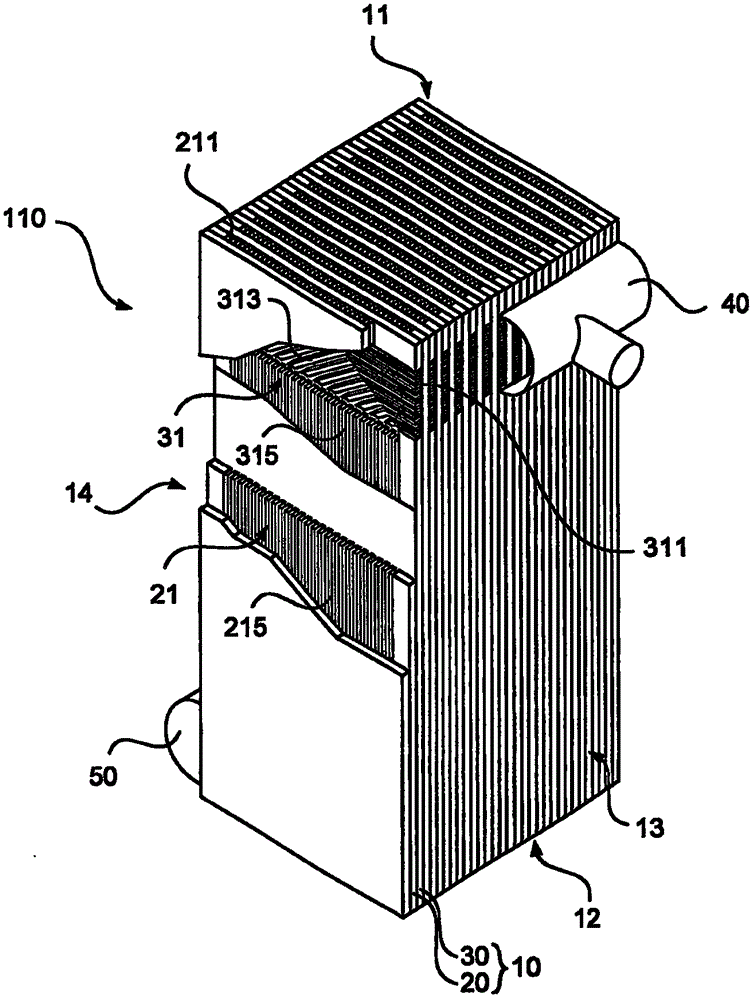
[0047] figure 1 A plate heat exchanger-condenser evaporator not according to the invention is shown schematically and partially opened. figure 1 The plate heat exchanger-condenser evaporator is indicated by 110 as a whole.

[0048] The heat exchanger block 10 of the plate heat exchanger-condenser evaporator is formed by an alternating arrangement of heat exchanger plates 20 and 30, wherein the heat exchanger plate 20 is hereinafter referred to as the "first" heat exchanger plate, and the heat exchanger The plate 30 is hereinafter referred to as the "second" heat exchanger plate. The corresponding heat exchanger plates are also described in more detail in the accompanying figures. Only two corresponding heat exchanger plates 20 , 30 are marked with reference symbols, however all heat exchanger blocks 10 are built up entirely from corresponding heat exchanger plates 20 , 30 .

[0049] Not only in the first heat exchanger plate 20 but also in the second heat exchanger plate 30...


PUM


Abstract

The present invention relates to a plate heat exchanger--capacitor evaporator with a heat exchanger block (10), and the plate heat exchanger--capacitor evaporator has a plurality of heat exchanger plates (20, 30) with a liquid guide structure (21, 31) ; the heat exchanger block (10) has a first outer surface (11), a second outer surface (12) opposite the first outer surface (11), a third outer surface (13) and a fourth outer surface (14) opposite to the third outer surface (13); the liquid guide structure (21) of the first heat exchanger plate (20) has first and second openings (211, 212) which are not covered by a liquid introduction pipe and a liquid collection pipe; the liquid guide structure (31) of the second heat exchanger plate (31) extends between a liquid introduction pipe (40) arranged on the heat exchanger block (10) and a liquid collection pipe (50) arranged on the heat exchanger block (10); the liquid introduction pipe (40) is arranged on the first outer surface (11); the first opening (211) of the liquid guide structure (21) of the first heat exchanger plate (20) is either arranged in a region of the first outer surface (11) which is not covered by the liquid introduction pipe (40), or is arranged on a first area of the third outer surface (13) and a first area of the fourth outer surface (14).

Description

technical field [0001] The present invention relates to a plate heat exchanger-condenser evaporator and a method for low-temperature decomposition of air according to the general concept of the independent claim. Background technique [0002] Can be used for different purposes in air splitting plants, among other things as main condenser or head condenser of (crude) argon column, combined evaporation and condensation unit. [0003] For example, as H.-W.Haring (Hrsg.) in its Industrial Gases Processing, Wiley-VCH, Weinheim: 2006, page 52 to 53 "Apparatus (device)" paragraph 2.2.5.6 or "Combined Evaporator / Condenser- Heat Transfer Units (Combined Evaporator / Condenser-Heat Exchange Unit)" subparagraph, here generally refers to the special form of plate heat exchanger (English, Plate Fin Heat Exchangers (plate fin heat exchanger)). Therefore, in the following the concept of plate heat exchanger-condenser evaporator is used for such a unit. [0004] For a professional understan...

Claims


Application Information

Patent Timeline
Patent Type & Authority Applications(China)
IPC IPC(8): F25J3/04F25J5/00
CPCF25J3/0406F25J3/04066F25J3/04072F25J5/00F25J5/005F25J2250/02F25J2290/32F28D9/0062F28D9/0068F28F3/025F28F9/02
Inventor T·黑希特W·基佩A·亚利
Owner LINDE AG
Why Eureka
Try Eureka