
Dust removal nozzle and dust removal device

A nozzle and gas ejection technology, applied in the direction of spraying devices, cleaning methods and appliances, chemical instruments and methods, etc., can solve the problems of reduced cleaning efficiency, consumption, and disconnection of small faces, so as to reduce air consumption and improve cleaning efficiency effect

Active Publication Date: 2019-06-14
TAKUSYO CO LTD
View PDF8 Cites 0 Cited by
  • Summary
  • Abstract
  • Description
  • Claims
  • Application Information

AI Technical Summary

Problems solved by technology

Due to the consumption of excess air in parts other than the small face, there is a disadvantage that the cleaning efficiency of the important small face that most needs dust removal is reduced
In addition, in general, there are many ultra-thin wires with a diameter of tens of microns outside the small surface, and the ultra-thin wires may be disconnected or damaged by blowing high-pressure and high-speed gas.

Method used


Image

  • Dust removal nozzle and dust removal device
  • Dust removal nozzle and dust removal device
  • Dust removal nozzle and dust removal device

Examples


Embodiment Construction

[0022] Hereinafter, the present invention will be described in detail based on drawings showing embodiments.

[0023] Figure 4 One embodiment of a dust removal device having a dust removal nozzle according to the present invention is shown, and the device is used for dust removal and cleaning by blowing gas to an electronic component 6 partially equipped with a small surface area 2 to be dust removed. For example, the electronic components 6 are arranged in a grid or zigzag on a printed circuit board or a cassette tray, and dust removal nozzles 1 are arranged corresponding to each column of the electronic components 6, and one dust removal nozzle 1 is arranged relative to each One place on the electronic component 6 wants dust removal small face 2 to be opposite shape.

[0024] Such as image 3 As shown, the dust-removing small face 2 is made of sensors such as a CMOS image sensor or a CCD image sensor, for example. On the electronic component 6, the micro-fine wiring 8 is...


PUM


Abstract

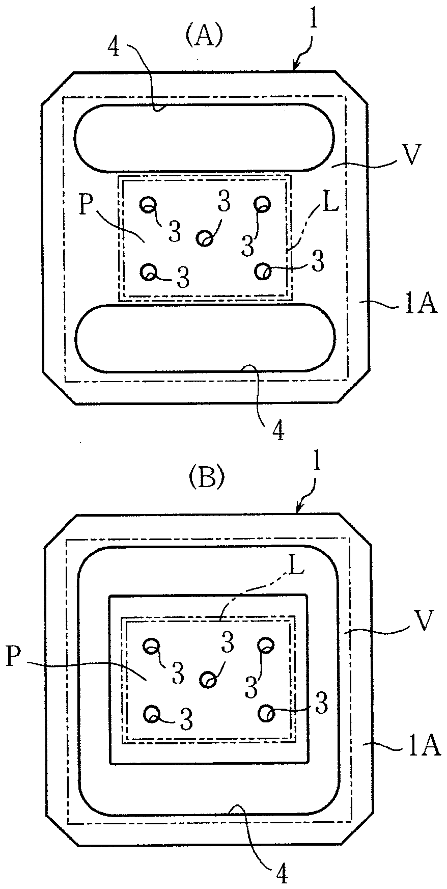
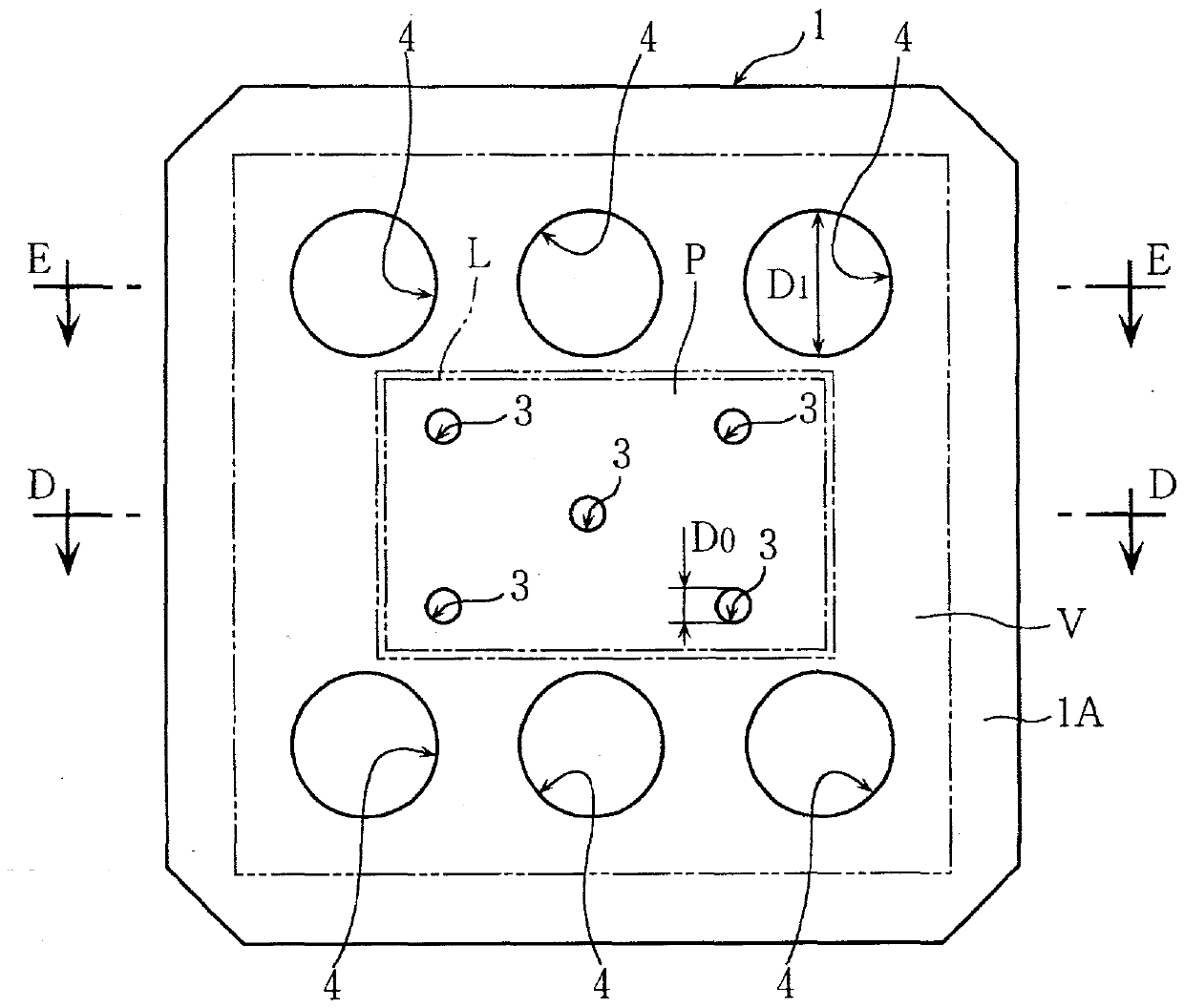
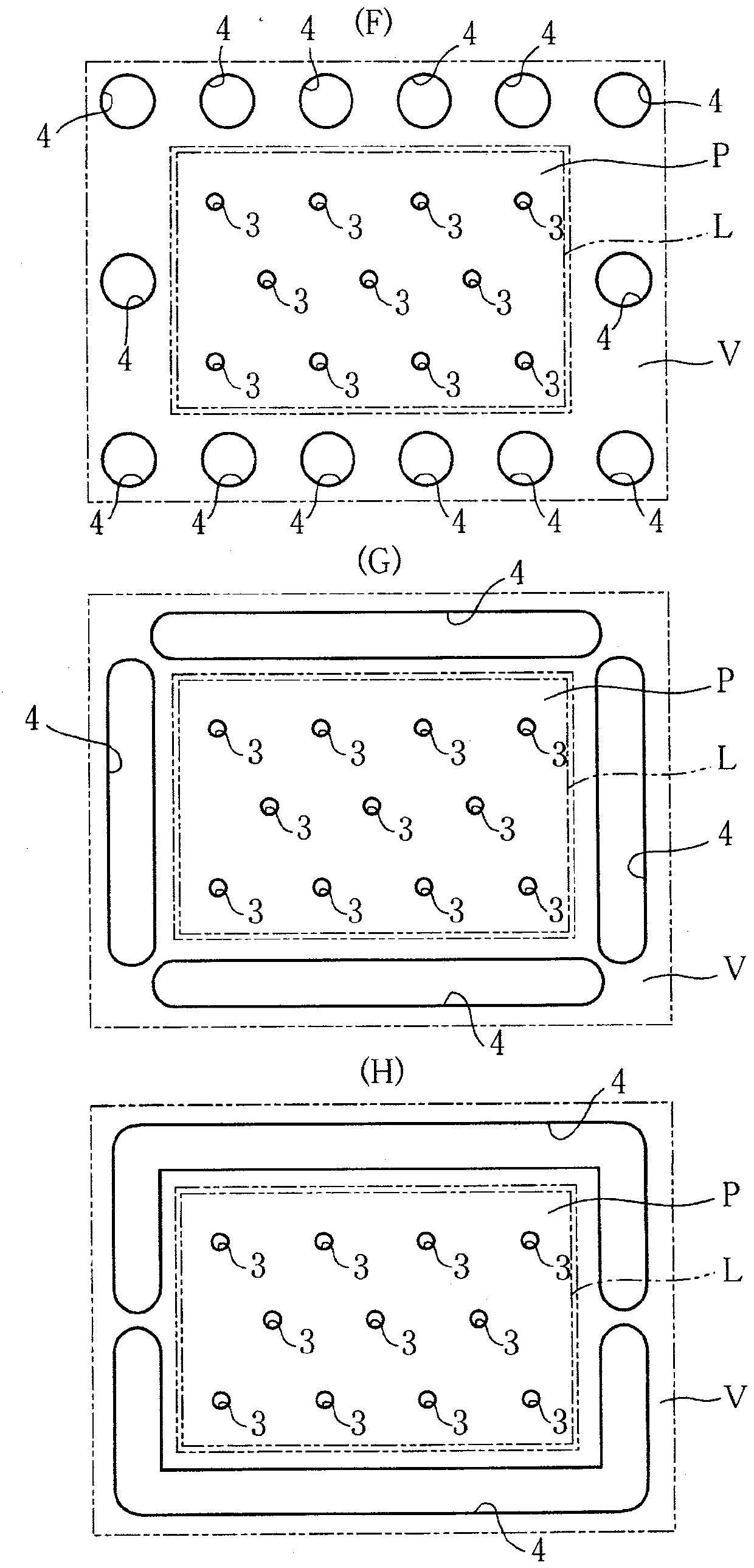
PROBLEM TO BE SOLVED: To provide a dust removing nozzle capable of intensively and efficiently cleaning the small area portion of a sensor and the like required for ultra-high cleanliness in electronic components.SOLUTION: A dust removing nozzle where an electronic component partly provided with a dedusting-needed small area portion required for ultra-high cleanliness is cleaned by air includes: air jetting holes 3 jetting air toward the inside of the outline L of the dedusting-needed small area portion; and air suction holes 4 arranged so as to surround the air jetting holes 3 and suctioning air at the outside of the outline of the dedusting-needed small area portion.SELECTED DRAWING: Figure 1

Description

technical field [0001] The invention relates to a dust removal nozzle and a dust removal device. Background technique [0002] For example, small (small) electronic components including CMOS image sensors, CCD image sensors, etc. are arranged in multiple rows on printed circuit boards or cassette trays, and flow on the production line. [0003] The above-mentioned small parts in (small) electronic components are parts where ultra-high cleanliness is particularly required. Conventionally, there is known a dust removal device that removes foreign matter such as dust and fine particles adhering to the above-mentioned small surface area by blowing out or sucking gas (see Patent Document 1). [0004] Patent Document 1: Japanese Patent Laid-Open No. 2014-100622. [0005] However, the conventional dust remover removes dust and cleans dust by blowing gas to parts other than the above-mentioned small face parts by a horizontally long cleaning head (dust removal head) that correspon...

Claims


Application Information

Patent Timeline
Patent Type & Authority Patents(China)
IPC IPC(8): B08B5/02B08B5/04B05B13/02
CPCB05B13/0278B08B5/023B08B5/043
Inventor 宇泽启久保孝夫
Owner TAKUSYO CO LTD
Learn More