
Light spot machine debugging system and light spot machine debugging method for medium/long-working-distance single-mode single-fiber collimators

A technology of working distance and debugging system, which is used in optical instrument testing, testing of optical fiber/optical waveguide equipment, and testing of machinery/structural components, etc. The effect of debugging accuracy, high pair-matching, and improving work efficiency

Active Publication Date: 2017-03-15
上海中科光纤通讯器件有限公司 +2
View PDF10 Cites 5 Cited by
  • Summary
  • Abstract
  • Description
  • Claims
  • Application Information

AI Technical Summary

Problems solved by technology

Fully automatic debugging generally at least through the automatic adjustment frame and optical power detector or beam quality analyzer or a combination of the two, the equipment in this debugging system is relatively large, and it is expensive and prone to failure, and the settings in the equipment are relatively complicated , the debugging system is too dependent on the judgment made by the equipment, thus reducing the subjective initiative of people

Method used


Image

  • Light spot machine debugging system and light spot machine debugging method for medium/long-working-distance single-mode single-fiber collimators
  • Light spot machine debugging system and light spot machine debugging method for medium/long-working-distance single-mode single-fiber collimators
  • Light spot machine debugging system and light spot machine debugging method for medium/long-working-distance single-mode single-fiber collimators

Examples


Embodiment Construction

[0063] In order to describe the technical content of the present invention more clearly, further description will be given below in conjunction with specific embodiments.

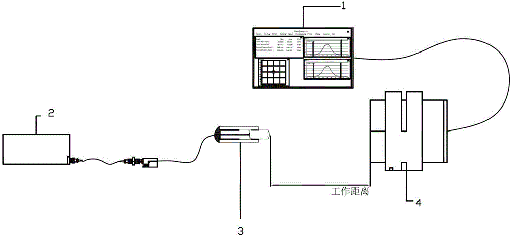
[0064] The spot machine debugging system of the medium and long working distance single-mode single-fiber collimator is characterized in that the debugging system includes a laser point light source, an adjustment frame, and a medium-long working distance single-mode single-fiber collimator arranged in sequence and a spot machine, the spot machine includes a probe, and the probe is movably installed in the debugging system, and the middle and long working distance single-mode single-fiber collimator is connected with the laser point light source , the medium and long working distance single-mode single-fiber collimator includes a single-mode single-fiber pigtail, a lens and a glass tube, and the single-mode single-fiber pigtail is movably installed on the adjustment frame, the The lens and the adjustment fr...


PUM


Abstract

The invention relates to a light spot machine debugging system and a light spot machine debugging method for medium / long-working-distance single-mode single-fiber collimators. The system comprises a laser point light source, a light spot machine, a medium / long-working-distance single-mode single-fiber collimator, a five-dimensional adjusting frame, and a sliding table. The laser point light source is connected with the medium / long-working-distance single-mode single-fiber collimator. The light spot machine is connected with a computer. The medium / long-working-distance single-mode single-fiber collimator is arranged on the five-dimensional adjusting frame. The light spot machine is arranged on the sliding table. By using the light spot machine debugging system and the light spot machine debugging method for medium / long-working-distance single-mode single-fiber collimators, the light path debugging difficulty is reduced, the debugging precision is improved, the medium / long-working-distance single-mode single-fiber collimator has smaller insertion loss and higher degree of pairing, and the consistency and first-pass yield of products are higher, the debugging time is reduced, and the work efficiency of employees is improved. The system and the method are also applicable to medium / long-working-distance single-mode single-fiber collimators of which the medium / long working distance is at specific bands, such as 850nm and 1060nm.

Description

technical field [0001] The invention relates to the technical field of optical fiber communication, in particular to the technical field of optical path debugging, and specifically refers to a spot machine debugging system and method for a single-mode single-fiber collimator with a medium and long working distance. Background technique [0002] At present, the common debugging system of the single-mode single-fiber collimator with medium and long working distance is the reflection method, transmission method or automatic debugging through the fine-tuning frame; the reflection method debugging is to use the mirror with the corresponding wavelength bandwidth at half of the working distance The reflection method debugs the single-mode single-fiber collimator with medium and long working distance to minimize the reflection insertion loss. The optical path includes a laser point light source of corresponding wavelength, a splitting fiber coupler, a reflector of corresponding wave...

Claims


Application Information

Patent Timeline
Patent Type & Authority Applications(China)
IPC IPC(8): G01M11/00
CPCG01M11/33
Inventor 叶雪梅
Owner 上海中科光纤通讯器件有限公司
Learn More