
Back-flushing filtration system and filtration method for cutting fluid

A filtration system and cutting fluid technology, applied in fixed filter element filters, filtration circuits, filtration separation, etc., can solve the problems of no filter element self-cleaning function, the filtration efficiency needs to be improved, and the high precision is not satisfied, and the structure is simple, The effect of long service life and small footprint

Pending Publication Date: 2017-03-15
江苏威泽智能科技股份有限公司
View PDF20 Cites 4 Cited by
  • Summary
  • Abstract
  • Description
  • Claims
  • Application Information

AI Technical Summary

Problems solved by technology

[0004] The above scheme improves the problem of large waste of consumables and high cost of the existing cutting oil filter, and has the advantages of no secondary pollution and no consumable filtration. However, this scheme still does not meet the needs of high precision, and the filtration efficiency needs to be improved. No defects such as filter self-cleaning function

Method used


Image

  • Back-flushing filtration system and filtration method for cutting fluid
  • Back-flushing filtration system and filtration method for cutting fluid
  • Back-flushing filtration system and filtration method for cutting fluid

Examples


Embodiment Construction

[0031] The present invention will be described in further detail below in conjunction with the accompanying drawings and specific embodiments.

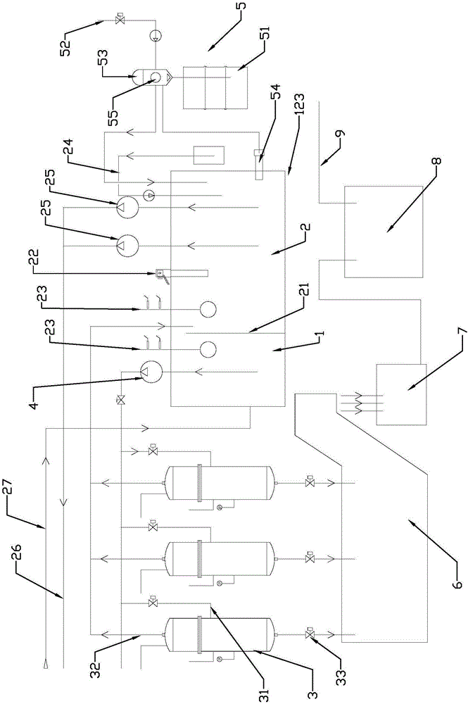
[0032] like Figure 1-3 As shown, in this embodiment, the recoil type cutting fluid filtration system includes a liquid storage box 123 with a dirty liquid chamber 1 and a clean liquid chamber 2, and a belt scraper 22 and The liquid level monitor 23 located in the dirty liquid chamber 1 and the clean liquid chamber 2, and the outside of the liquid storage box 123 is provided with a sterilizing and dosing mechanism 24 connected with the clean liquid chamber 2, the dirty liquid inlet of the dirty liquid chamber 1 is connected to the The dirty liquid return pipe 27 of the machine tool is connected, the clean liquid outlet of the clean liquid chamber 2 is connected with the clean liquid supply pipe 26 through the liquid supply pump 25, and at least one filter core 34 is provided on one side of the liquid storage box 123. Rush self-cleani...


PUM


Abstract

The invention provides a back-flushing filtration system and filtration method for a cutting fluid, belonging to the technical field of machining equipment. The back-flushing filtration system and filtration method overcome the technical problems of no self-cleaning capability and the like of conventional filter cores. The back-flushing filtration system comprises a fluid storage case provided with a dirty fluid chamber and a clean fluid chamber; the dirty fluid inlet of the dirty fluid chamber is communicated with a dirty fluid returning pipeline of a machine tool; the clean fluid outlet of the clean fluid chamber is connected with a clean fluid supply pipeline via fluid supply pumps; one side of the fluid storage case is provided with back-flushing self-cleaning filters equipped with filter core bodies; each back-flushing self-cleaning filter is provided with a filter inlet, a filter outlet and a blow-off valve and further provided with an evacuation and back-flushing structure capable of filling the filter inlet and / or the filter outlet with air; the dirty fluid outlet of the dirty fluid chamber is communicated with the filter inlets of the back-flushing self-cleaning filters via a filtering pump; and the filter outlets of the back-flushing self-cleaning filters are communicated with the clean fluid outlet of the clean fluid chamber. The back-flushing filtration system and filtration method have the advantages of high filtration accuracy and high filtering efficiency, and the filter cores have a self-cleaning function.

Description

technical field [0001] The invention belongs to the technical field of mechanical processing equipment, and in particular relates to a backflushing cutting fluid filtering system and a filtering method. Background technique [0002] People are performing mechanical processing. For example, metals such as tools and grinders need to use a large amount of cutting oil and cutting fluid to cool and protect the cooling tool and workpiece during product processing. Cutting oil and cutting fluid are always circulating in CNC machining. However, after using for a period of time, the cutting oil and cutting fluid will contain impurities such as metal chips, and they will deteriorate, discolor and stink. The tool damage of the CNC machining center will affect the machining accuracy of the workpiece, and it will also cause the workpiece to be discolored, and the smelly cutting oil and cutting fluid will also affect the health of workers on the production line. Therefore, the cutting oi...

Claims


Application Information

Patent Timeline
Patent Type & Authority Applications(China)
IPC IPC(8): B01D36/00B01D29/31B01D29/66B01D29/68
CPCB01D29/31B01D29/668B01D29/68B01D36/00B01D36/006B01D2221/14
Inventor 杨献春
Owner 江苏威泽智能科技股份有限公司
Learn More