A digital program-controlled constant current source

A program-controlled constant current source, digital technology, applied in control/regulating systems, regulating electrical variables, instruments, etc., can solve problems such as easily damaged loads and circuits, failure to take protective measures in time, and burnout of power tubes.

Active Publication Date: 2017-09-29
JILIN UNIV
View PDF5 Cites 0 Cited by
  • Summary
  • Abstract
  • Description
  • Claims
  • Application Information

AI Technical Summary

Problems solved by technology

Among these schemes, the first scheme is greatly affected by the device itself and has limited improvement in stability; the second scheme can effectively reduce the impact of changes in load resistance due to a large resistor connected in series in the load circuit. The influence of the output current, but due to the existence of a large resistance in the load circuit, the output current is very small when the power supply voltage is constant, generally only in the milliampere level, and most of the voltage is dropped on the large resistance. The efficiency is extremely low; the third scheme is the most effective way to improve current stability because of the automatic adjustment function of the negative feedback network itself, which can automatically stabilize the output current without being affected by load changes. In the disclosed technology, a single linear feedback network is generally adopted. The disadvantages of this scheme are: first, once the feedback network fails, the system will be in an open-loop working state, and the output current will increase sharply, which is easy to damage the load and the circuit itself; secondly, the use occasions are limited, and can only be applied to occasions where the load responds linearly to the current. The constant current effect of the constant current source of the network will be greatly reduced
[0004] However, the technology disclosed in the patent 201511009383X is completely realized based on analog circuits. This circuit has many disadvantages. The function is relatively single. Redesign and production of hardware circuits greatly restrict the scalability and flexibility of the system
In addition, the patent 201511009383X still has certain deficiencies in system safety: 1. The system does not have a voltage monitoring module. Once the load is too small or short-circuited, the entire power supply voltage will drop at both ends of the internal power tube. Larger power is produced, which burns out the power tube; 2. The system does not have a temperature monitoring module. When the system is improperly used or some unpredictable factors cause the main components of the circuit to overheat, effective protection measures cannot be taken in time; 3. The system starts When outputting current, the output current directly reaches the set value. This steep current rising edge will cause power-on shock to the load and reduce the service life of the load.

Method used


Image

  • A digital program-controlled constant current source
  • A digital program-controlled constant current source
  • A digital program-controlled constant current source

Examples


Embodiment 1

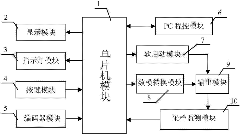
[0039] Embodiment 1 Overall structure of the system

[0040] Such as figure 1 and Figure 12 As shown, the system structure includes MCU module 1, display module 2, indicator module 3, button module 4, encoder module 5, PC program control module 6, soft start module 7, digital-to-analog conversion module 8, output module 9, sampling monitoring Module 10 and front panel 11.

Embodiment 2

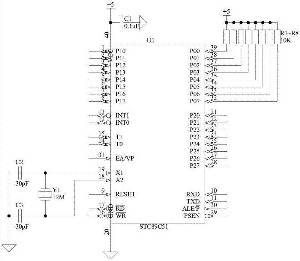
[0041] Embodiment 2 Single-chip microcomputer module

[0042] Such as figure 2 As shown, the structure of the single-chip microcomputer module 1 is that the power supply terminal and the ground terminal of the single-chip microcomputer U1 are connected to +5V power supply and digital ground respectively, the power supply terminal is also connected to the digital ground through the capacitor C1, and the crystal oscillator Y1 is connected between the port X1 and the port X2. Port X1 and port X2 are also connected to digital ground through capacitor C2 and capacitor C3 respectively, and ports P00 to port P07 are respectively connected to +5V power supply through resistors R1 to R8. ), P1 mouth (P10~P17), P2 mouth (P20~P27) are common input / output ports, use P0 mouth in the present invention as the data exchange mouth of single-chip microcomputer and A / D, D / A and display chip, P2 Each pin of the port and P3 port is used as the control terminal to realize the coordinated work of ...

Embodiment 3

[0043] Embodiment 3 Display module

[0044] Such as image 3As shown, the structure of the display module 2 is that the ports D0-D7 of the display screen U2 are respectively connected to the ports P00-P07 of the single-chip microcomputer U1, and the ports EN, port R / W and port RS of the display screen U2 are connected to the single-chip microcomputer respectively. Port P10, port WR and port RD of U1, port VL and port BL- of display screen U2 are connected to digital ground, port BL+ is connected to the sliding wire end of sliding rheostat P1, port VDD and port VSS are respectively connected to +5V power supply and digital ground, A capacitor C4 is also connected between the port VDD and the port VSS, one end of the sliding rheostat P1 is connected to a +5V power supply, and the other end is connected to a digital ground. The model of the display screen U2 is LCD1602, which is a 16*2 integrated liquid crystal display with 14 pins in total. The port VDD and the port VSS are the...


PUM


Abstract

The invention discloses a digital program-control constant current source, and belongs to the technical field of electronic equipment. The digital program-control constant current source structurally comprises an output module (9) and a front panel (11), and is characterized by further structurally comprising a single chip microcomputer module (1), a display module (2), an indicator lamp module (3), a key module (4), an encoder module (5), a program control (PC) module (6), a soft starting module (7), a digital-to-analog conversion module (8) and a sampling monitoring module (10). The digital program-control constant current source is based on single chip microcomputer control, and has the advantages of being rich in function, convenient to upgrade, capable of achieving program control and the like; in addition, the digital program-control constant current source has the functions of over-temperature alarming, low-pressure alarming, soft starting and the like, and is high in safety and wide in application range.

Description

technical field [0001] The invention belongs to the technical field of electronic equipment, in particular to a digital program-controlled constant current source device. Background technique [0002] Constant current sources have important applications in many fields such as LED drive, laser drive, sensor drive, and various glow discharge light source drives. In some specific application fields, the stability of the output current of the constant current source is very important. For example, in the laser driving application, a small current change will cause a large change in the output optical power and lasing wavelength, and these changes will directly endanger the device. safe use. Commonly used measures to improve current stability include: 1. Using the nonlinear magnetization principle of magnetic saturation reactor to improve stability; 2. Connecting a large resistance in series in the load circuit (relative to the load resistance); 3. Realizing the current through ...

Claims


Application Information

Patent Timeline
Patent Type & Authority Patents(China)
IPC IPC(8): G05F1/56
CPCG05F1/561
Inventor 汝玉星田小建高博单江东吴戈高福斌李尚安明梁雪刘大恺马春阳
Owner JILIN UNIV
Why Eureka
Try Eureka