Metal foil for current collector, current collector, and method for manufacturing metal foil for current collector
A current collector and metal foil technology, which is applied in the manufacture of hybrid/electric double layer capacitors, non-aqueous electrolyte battery electrodes, battery electrodes, etc., can solve problems such as difficulty in maintaining equipment performance for a long time, reduced charge and discharge characteristics, and reduced equipment performance , to achieve the effect of reducing electrode resistance, improving charge and discharge characteristics, and reducing contact resistance
- Summary
- Abstract
- Description
- Claims
- Application Information
AI Technical Summary
Problems solved by technology
Method used
Image

Examples
Embodiment 1
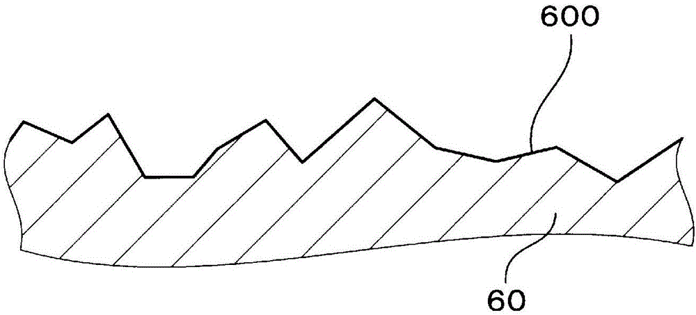
[0070] A pair of roughening rollers 6 are prepared in advance in the following procedure. First, a pair of rolling rolls 60 are subjected to shot peening processing using projection grid particles with a particle size of 40 μm, and the surfaces 600 of the two rolling rolls 60 are image 3 The surface is roughened as shown. Next, the surface 600 of the rolling roll 60 is subjected to chromium plating treatment to form a chromium plating film 61. The chromium plating treatment is carried out in a Sargent bath containing 250g / L of chromic anhydride and 2.5g / L of sulfuric acid at a temperature of 50℃ and a current density of 30A / dm 2 Conditions. The film thickness of the chromium plating film 61 is 5 μm. Such as Figure 4 As shown, the chromium plating film 61 has a plurality of substantially spherical convex portions 610 by preferentially adhering to the sharp portion of the surface 600.
[0071] After that, the pair of rolling rolls 60 on which the chromium plating film 61 was fo...
Embodiment 2
[0075] Except that the particle size of the projection grid particles and the rolling load in the step of crushing the top of the chrome plating film 61 were changed to the conditions shown in Table 1, a pair of roughening rollers 6 were produced in the same manner as in Example 1. Using the obtained roughened roll 6, the surface shape was transferred to a rolled copper foil having a thickness of 10 μm under the same conditions as in Example 1 to obtain a metal foil E2. The average L of the Fret diameter of the concave part 4 on the metal foil E2 ave It is 10.1 μm, and the depth of the concave portion 4 is 2.0 μm at the deepest.
Embodiment 3
[0077] Except that the particle size of the projection grid particles and the rolling load in the step of crushing the top of the chrome plating film 61 were changed to the conditions shown in Table 1, a pair of roughening rollers 6 were produced in the same manner as in Example 1. Using the obtained roughened roll 6, the surface shape was transferred to a rolled copper foil having a thickness of 10 μm under the same conditions as in Example 1 to obtain a metal foil E3.
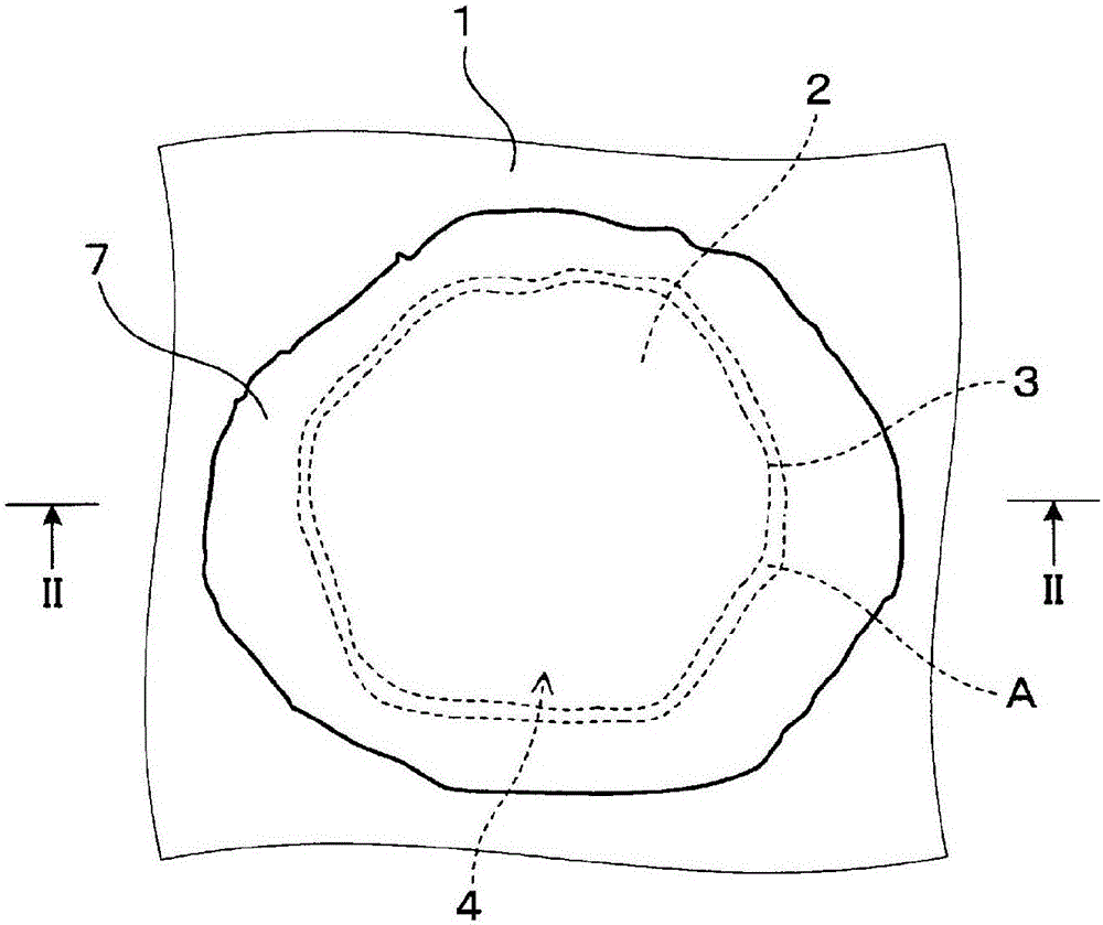
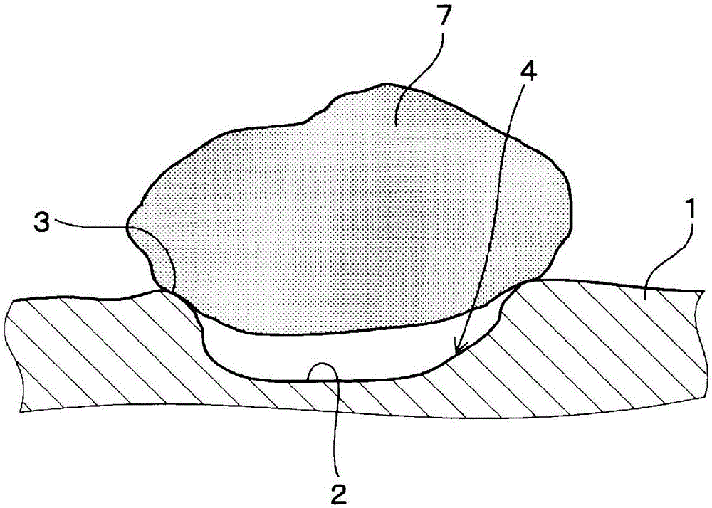
[0078] As an example of the metal foil 1 having a plurality of concave portions, Image 6 It shows the SEM (scanning line electron microscope) image of the roughened surface of the metal foil E3. Such as Image 6 It can be seen that the roughened surface of the metal foil E3 is formed with a plurality of concave portions 4 having a substantially circular shape, a substantially elliptical shape, or a shape in which these are overlapped. In addition, the presence of rolling traces or oil pits during foil rolling i...
PUM
| Property | Measurement | Unit |
|---|---|---|
| depth | aaaaa | aaaaa |
| particle diameter | aaaaa | aaaaa |
| mean roughness | aaaaa | aaaaa |
Abstract
Description
Claims
Application Information
 - Generate Ideas
- Intellectual Property
- Life Sciences
- Materials
- Tech Scout
- Unparalleled Data Quality
- Higher Quality Content
- 60% Fewer Hallucinations
Browse by: Latest US Patents, China's latest patents, Technical Efficacy Thesaurus, Application Domain, Technology Topic, Popular Technical Reports.
© 2025 PatSnap. All rights reserved.Legal|Privacy policy|Modern Slavery Act Transparency Statement|Sitemap|About US| Contact US: help@patsnap.com