Angle valve and angle valve manufacturing process and positioning tool
A technology of manufacturing process and positioning tooling, applied in valve device, valve details, valve shell structure and other directions, can solve the problems of poor surface consistency of triangle valve, difficult polishing, increase production cost, etc., and achieve smooth connection and metallographic appearance. The effect of small variation range and improved welding quality
- Summary
- Abstract
- Description
- Claims
- Application Information
AI Technical Summary
Problems solved by technology
Method used
Image

Examples
Embodiment 1
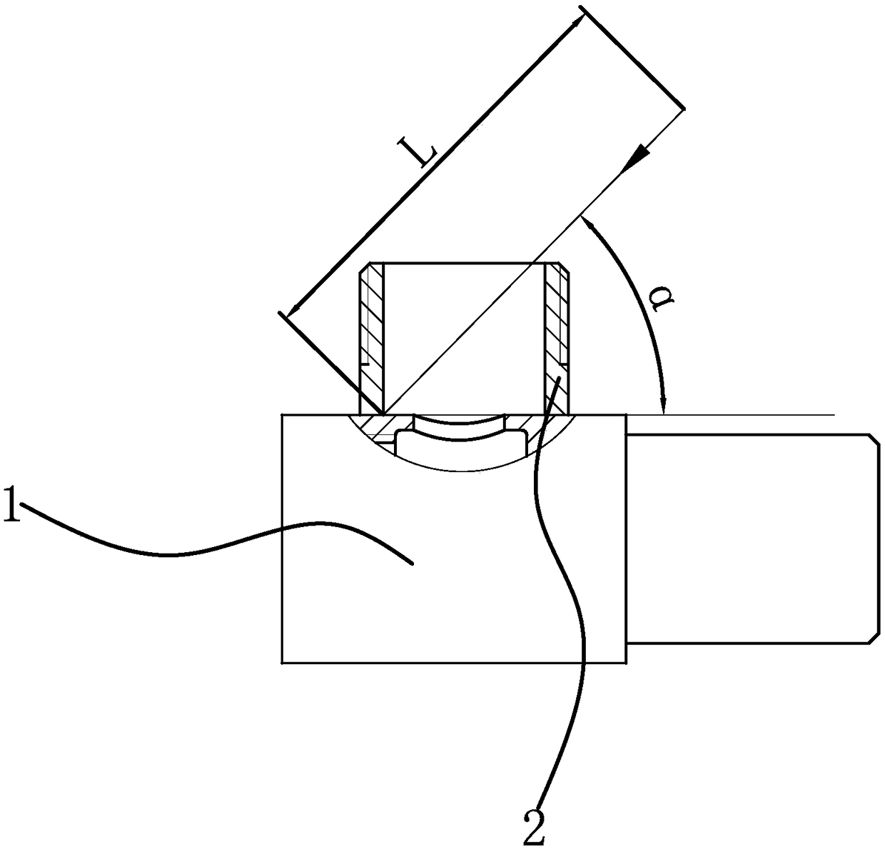
[0054] Such as Figure 7 and Figure 8 As shown, the angle valve includes an angle valve main body 1 and an angle valve joint 2, the angle valve joint 2 is cylindrical, the angle valve joint 2 is fixed on the angle valve main body 1 to form a valve body, and the valve body has a valve cavity. The spool is loaded into the valve cavity from one end of the angle valve main body 1, and a handle is installed on the spool. The angle valve joint 2 communicates with the valve cavity, and the other end of the angle valve main body 1 serves as the water inlet and outlet of the angle valve respectively.
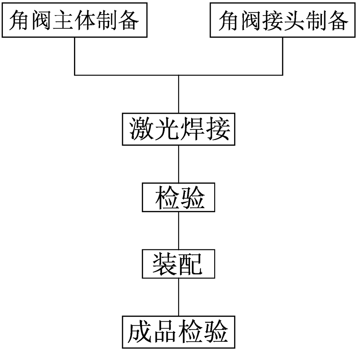
[0055] Such as figure 1 As shown, the manufacturing process of this angle valve includes the following steps:
[0056] a. Preparation of the main body of the angle valve: the raw materials are cut according to the shape and size of the main body of the angle valve 1, the surface is processed and then drilled through the water hole 1a to obtain the main body of the angle valve 1.
[...
Embodiment 2
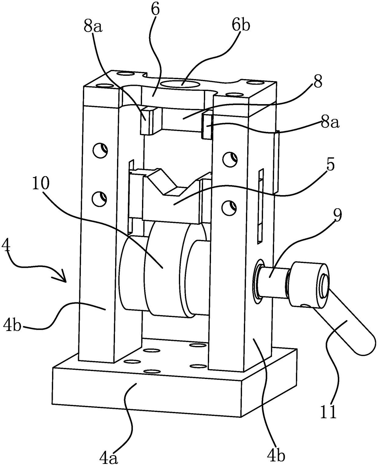
[0069]This embodiment discloses a positioning tool for positioning the angle valve main body 1 and the angle valve joint 2 in the angle valve manufacturing process of the first embodiment.
[0070] Such as image 3 and Figure 4 As shown, the positioning tooling of the angle valve includes a frame body 4, a V-shaped block 5, a positioning plate 6 and a mandrel 7. The frame body 4 includes a base 4a for shifting the bottom and vertical plates 4b fixed on both sides of the base 4a. A positioning plate 6 is fixed on the upper part of the vertical plate 4b. The positioning plate 6 has an abutment surface 6a and a relief opening 6b. The two sides of V-shaped block 5 have slide block respectively, and the position corresponding to vertical plate 4b and slide block has the chute that matches with slide block, and slide block can slide up and down in corresponding chute so that V-shaped block 5 can be relatively Slide on frame body 4. The frame body 4 is also provided with a drivin...
Embodiment 3
[0075] This embodiment discloses the angle valve manufactured by the angle valve manufacturing process of Embodiment 1, such as Figure 7 and Figure 8 As shown, the angle valve includes an angle valve body 1 and an angle valve joint 2. The angle valve joint 2 is fixed on the angle valve body 1 by welding. One end of the angle valve joint 2 has an arc connection that matches the shape of the outer wall of the angle valve body 1. surface 2a, and when the angle valve joint 2 is installed on the angle valve main body 1, the arc-shaped connection surface 2a is attached to the outer wall of the angle valve main body 1, and the weld 3 between the angle valve main body 1 and the angle valve joint 2 is located inside the angle valve joint 2 . In this embodiment, the angle valve main body 1 and the angle valve joint 2 are fixed by laser welding.
[0076] Such as Figure 7 As shown, there is a valve cavity in the angle valve main body 1, and there is a water passage hole 1a connected...
PUM
| Property | Measurement | Unit |
|---|---|---|
| length | aaaaa | aaaaa |
| angle of incidence | aaaaa | aaaaa |
Abstract
Description
Claims
Application Information
 - R&D
- Intellectual Property
- Life Sciences
- Materials
- Tech Scout
- Unparalleled Data Quality
- Higher Quality Content
- 60% Fewer Hallucinations
Browse by: Latest US Patents, China's latest patents, Technical Efficacy Thesaurus, Application Domain, Technology Topic, Popular Technical Reports.
© 2025 PatSnap. All rights reserved.Legal|Privacy policy|Modern Slavery Act Transparency Statement|Sitemap|About US| Contact US: help@patsnap.com