Ore smashing device

A technology of ore crushing and crushing roller, which is applied in the field of mining machinery, can solve the problems of clogging the crushing shaft, affecting the quality of ore crushing, and poor crushing effect

Inactive Publication Date: 2017-02-15
耒阳市华兴机械有限公司
View PDF7 Cites 13 Cited by
  • Summary
  • Abstract
  • Description
  • Claims
  • Application Information

AI Technical Summary

Problems solved by technology

[0003] According to the different types of crushing parts, ore crushers are generally divided into two principles: mechanical crushing and airflow crushing. The selection of crushing parts is not only affected by the shape and texture of raw materials, but also restricted by the principle size required for subsequent production. , the existing pulverizer crushes relatively large ore, causing larger particles to block the crushing shaft, causing damage to the conveying device, and causing uneven particle size of the product, which affects the final crushing quality of the ore
[0004] In order to solve the problem of blockage of the crushing circle caused by ore with large particle size, Chinese patent CN205731541U discloses a kind of ore crusher, including a crushing box, a hydraulic device is installed on the top of the crushing box, and a feeding pipe is provided on the left side of the top. There is a hydraulic rod at the center of the inner cavity, and a gravity hammer is arranged at the bottom of the hydraulic rod; a bearing plate is arranged at the bottom of the inner cavity of the crusher box, and a through hole is arranged on the upper surface of the bearing plate; There is a connecting pipe, a crushing box is arranged at the bottom of the connecting pipe, a controller is arranged on the outer wall of the crushing box, the controller is electrically connected with the hydraulic device, and a crushing shaft is arranged at the center of the inner cavity of the crushing box. There are protective plates on the left and right sides, and a sloping plate at the lower end of the crushing shaft
However, the heavy vertical hammer of this pulverizer still has the problems of poor pulverization effect and low efficiency

Method used


Image

  • Ore smashing device
  • Ore smashing device

Examples


Embodiment Construction

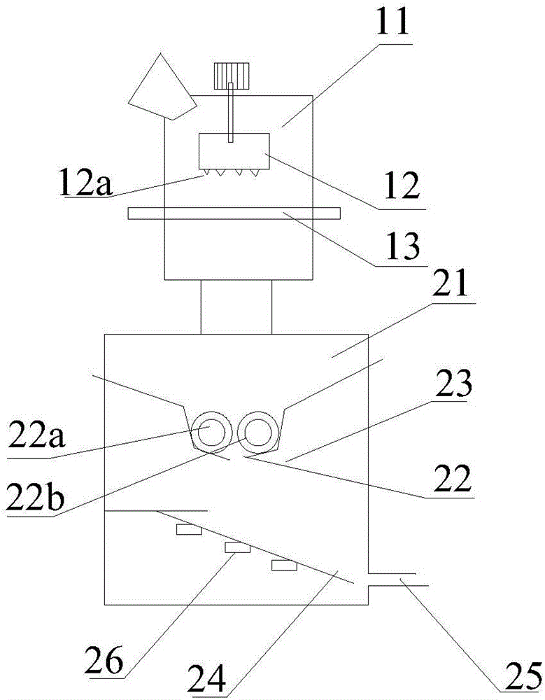
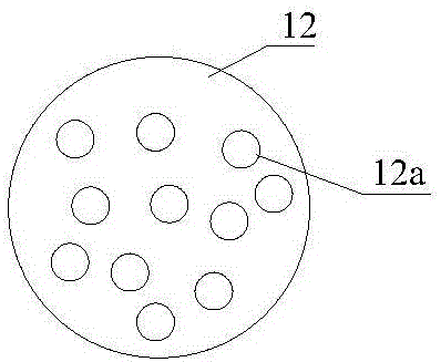
[0021] Please see attached figure 1 , is a schematic diagram of an embodiment of the ore crushing device provided by the present invention, specifically including a crusher box 11, a gravity hammer 12 is arranged in the crusher box, and a load-bearing plate 13 is arranged below the gravity hammer 12. The load-bearing plate is provided with sieve holes. In order to better crush the ore materials, a plurality of crushing cones are provided on the lower end surface of the gravity hammer provided by the present invention. Please also refer to figure 2 , the crushing cone is conical or pyramidal, and the present invention is not particularly limited thereto, preferably conical. The crushing cone can be machined on the gravity hammer, or directly fixed under the gravity hammer.

[0022] Due to the arrangement of the crushing cone, the gravity hammer can achieve better crushing effect during the reciprocating motion. There is a feeding port on the top of the crusher box. In order...


PUM


Abstract

The invention discloses an ore smashing device. The ore smashing device comprises a breaking machine box and a smashing box arranged under the breaking machine box; a gravity hammer is installed in the breaking machine box, a bearing plate is arranged below the gravity hammer and is provided with screening holes, and a plurality of breaking cones are arranged on the lower end face of the gravity hammer; and a smashing roller set is installed in the smashing box and comprises two opposite smashing rollers. Compared with the prior art, the ore smashing device has the advantages that the breaking cones arranged at the bottom end of the gravity hammer can break ores better, the smashing roller set installed in the smashing box can grind the broken ores better, and therefore better smashing effect can be realized.

Description

technical field [0001] The invention relates to the technical field of mining machinery, in particular to an ore crushing device. Background technique [0002] Mineral resources are the material basis for the survival and development of contemporary human beings. Even with the rapid development of information technology today, mineral resources still play an irreplaceable role in human daily life. Ore crushing and grinding is an important link in the process of mineral resources processing, and it is also an operation with huge investment and high performance. As far as metal mines are concerned, equipment investment for crushing and grinding operations accounts for 65-75% of the total plant, electricity consumption is about 50-60%, and steel consumption is as high as 50%. Therefore, how to improve the performance of crushing and grinding equipment, develop energy-saving equipment for colleges and universities, obtain a larger crushing ratio, achieve a finer particle size o...

Claims


Application Information

Patent Timeline
IPC IPC(8): B02C1/00B02C4/02B02C23/16
CPCB02C1/005B02C4/02B02C23/16B02C2023/165
Inventor 尹毅雄
Owner 耒阳市华兴机械有限公司
Why Eureka
Try Eureka