
Grinding device

A grinding device and grinding body technology, which is applied in the fields of medicine, chemical industry, beverage emulsion, and biology. It can solve the problems of equipment grinding that cannot meet user needs, poor heat dissipation conditions, chemical solutions, and large powder particles, etc., and achieves convenient maintenance. , Uniform particle size and more output

Inactive Publication Date: 2017-02-08
HARBIN UNIV OF SCI & TECH
View PDF12 Cites 5 Cited by
  • Summary
  • Abstract
  • Description
  • Claims
  • Application Information

AI Technical Summary

Problems solved by technology

[0002] At present, biological, pharmaceutical, chemical, beverage and other enterprises urgently need a device with high fineness, but the grinding of existing equipment cannot meet the needs of users; the existing grinding devices are all three-stage grinding, and the ground powder particles It is still relatively large, and the heat dissipation conditions of the existing equipment are poor, so that the chemical reaction of the chemical solution due to the increase in temperature cannot meet the requirements. After a period of grinding, the rotor wears a lot, and the rotor needs to be replaced.

Method used


Image

  • Grinding device
  • Grinding device
  • Grinding device

Examples


Embodiment Construction

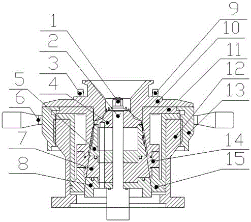
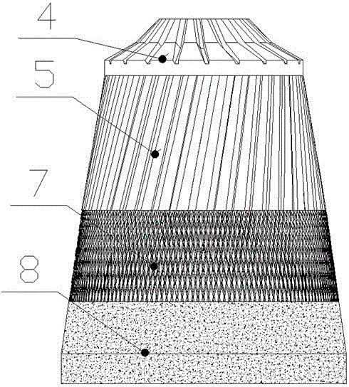
[0018] as attached figure 1 As shown, the grinding body consists of a main shaft 2, a third-stage static grinding body, a top cover 10, a fourth-stage dynamic grinding body, a casing 12, an adjusting disc 13, a handle 6, a lock nut 1, and inlet and outlet joints of coolant pipes; The device shell is fixed on the body. The upper end of the shell 12 has threads and the adjustment disc 13 to adjust the top cover 10 and the static grinding body; the dynamic grinding body is from thick to fine. The four-level tooth protrusions and grooves are used, and the fourth level is made of metal. The distance between the coating, the third-stage static grinding body and the top cover and the fourth-stage dynamic grinding body can be adjusted, and the fineness of the high-speed rotating grinding head is gradually increased to obtain micro-nano-scale material particles; the fourth-stage dynamic grinding body is fixed on the The main shaft 2 is locked by a lock nut at the front end of the main ...


PUM


Abstract

The invention discloses a grinding device mainly used as a grinding dispersion machine or a colloid mill. The grinding device is simple in structure, low in cost, convenient to machine and install, good in heat dissipation, suitable for high rotating speed and the like. The grinding device comprises a main shaft, three stages of static grinding bodies, a top cover, four stages of movable grinding bodies, a shell, an adjusting disk, a handle, a lock nut, a cooling liquid pipe inlet connector, a cooling liquid pipe outlet connector and the like. The movable grinding bodies are provided with four stages of sawtooth protrusions and grooves, the four stages of sawtooth protrusions and grooves become thin from thick, the fourth stage adopts a metal coating, and the distance between the three stages of static grinding bodies and the four stages of movable grinding bodies and the distance between the top cover and the four stages of movable grinding bodies can be adjusted; by means of a fineness-degree-increased grinding head rotating at a high speed, finally, micro-nano-level material particles are obtained; the four stages of movable grinding bodies are fixed to the main shaft and locked through the lock nut at the front end of the main shaft; the adjusting disk is arranged above the shell, the handle is installed on the adjusting disk, and the handle adjusts the adjusting disk so that the processing precision of materials in a cavity can be increased; and the top cover is arranged on the adjusting disk, the top cover is provided with the cooling liquid pipe inlet connector and the cooling liquid pipe outlet connector, the cooling liquid pipe inlet connector is connected with an annular cooling liquid channel, cooling liquid is added at any time, the adjusting disk, the materials and a grinding disk are protected, and the situation that the using performance is affected by the too-high temperature is avoided.

Description

technical field [0001] The invention mainly relates to the technical fields of medicine, biology, chemical industry and beverage emulsion, in particular to a grinding and dispersing machine and a colloid mill. Background technique [0002] At present, biological, pharmaceutical, chemical, beverage and other enterprises urgently need a device with high fineness, but the grinding of existing equipment cannot meet the needs of users; the existing grinding devices are all three-stage grinding, and the ground powder particles It is still relatively large, and the heat dissipation conditions of the existing equipment are poor, so that the chemical reaction of the chemical solution due to the temperature rise cannot meet the requirements. After a period of grinding, the rotor wears a lot, and the rotor needs to be replaced. Contents of the invention [0003] The technical problem to be solved by the present invention is to provide a method to reduce energy consumption, improve th...

Claims


Application Information

Patent Timeline
IPC IPC(8): B02C15/16B02C23/00
CPCB02C15/16B02C23/00
Inventor 郝广平石雷廖俊
Owner HARBIN UNIV OF SCI & TECH
Learn More