Glass mold polishing machine of improved structure

A glass mold and structure improvement technology, which is applied in the field of polishing machinery, can solve the problems of daily maintenance troubles, increase the overall height of the equipment, and affect the cooperation effect of the screw and the lifting nut of the lifting frame, so as to avoid the invasion of dust and save energy. Labor resources, the effect of improving the polishing effect

Active Publication Date: 2017-02-01
CHANGSHU JIANHUA MOLD TECH
View PDF5 Cites 4 Cited by
  • Summary
  • Abstract
  • Description
  • Claims
  • Application Information

AI Technical Summary

Problems solved by technology

The above-mentioned structure of using a horizontal lathe class as a polishing machine has the following deficiencies in the polishing of glass molds: the one is that the glass mold is in a lying state on the chuck, and the fine chips thrown off during the polishing process cannot be discharged completely and in time. Accumulated in the mold cavity, thus causing damage to the mold cavity; second, a worker can only serve one set of polishing machine, so it takes a lot of manpower and low efficiency; third, due to the use of a horizontal lathe structure, it will cause equipment waste of resources
[0003] The "polishing machine for glass moulds" provided by CN101659028B can make up for the aforementioned deficiencies and can objectively fulfill the technical effects recorded in the technical effect column of the description, but there are still the following shortcomings: First, due to the lifting motor of the patent It is installed vertically on the top of the frame (the patent is called "lifting slot column"), which increases the overall height of the equipment on the one hand, and causes troubles for daily maintenance on the other hand; The polishing head is in contact with the cavity wall of the glass mold and the polishing head is in a state of high-speed motion, so the temperature of the cavity rises sharply, so if a cooling lubricating medium such as lubricating liquid is not introduced into the cavity, there is a risk of heat generation or even a fire , lead to accidents, but the patent does not give the enlightenment to solve this problem; third, because the lower end of the screw rod that drives the lifting frame is formed as a vertical cantilever end, the screw rod will vibrate during the working process, which will affect the rotation of the screw rod Stability, which ultimately affects the smooth lifting effect of the lifting frame; Fourth, because the screw is exposed on the front of the screw cavity of the rack (the patent is called "lifting slot column"), that is, the front of the slot cavity, on the one hand, the screw is vulnerable to operation. Invasion of dust in the place will affect the cooperation effect between the screw and the lifting nut of the lifting frame, and on the other hand, it will lose safety

Method used


Image

  • Glass mold polishing machine of improved structure

Examples


Embodiment Construction

[0018] In order to understand the technical essence and beneficial effects of the present invention more clearly, the applicant will describe in detail the following examples, but the descriptions of the examples are not intended to limit the solutions of the present invention. Equivalent transformations that are only formal but not substantive should be regarded as the scope of the technical solution of the present invention.

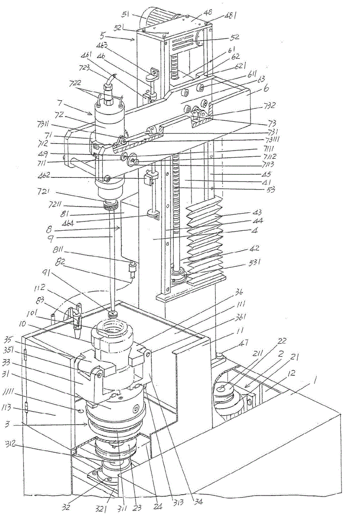
[0019] In the following descriptions, all concepts involving directionality or orientation of up, down, left, right, front and rear are aimed at figure 1 As far as the position state shown is concerned, it cannot be understood as a special limitation on the technical solution provided by the present invention.

[0020] See figure 1 , shows a machine base 1, the machine base 1 is set on the floor of the polishing work place in the use state, and an enclosure box 11 is arranged on the upper part of the machine base 1, and the upper part of the enclosure...


PUM


Abstract

A glass mold polishing machine of an improved structure comprises a machine base, a chuck driving mechanism, a bottle mold clamping and placing mechanism, a machine frame, a lifting-frame lifting driving mechanism, a lifting frame and a polishing mechanism, wherein an enclosure box is arranged on the upper portion of the machine base, a machine base cavity is arranged in the lower portion of the machine base, the chuck driving mechanism is arranged in the machine base cavity, the bottle mold clamping and placing mechanism is arranged in a cavity of the enclosure box, the machine frame is fixed to the upper portion of the machine base, the lifting-frame lifting driving mechanism is arranged on the machine frame, the lifting frame is arranged on the machine frame, and the polishing mechanism is arranged on the lifting frame. The lifting-frame lifting driving mechanism comprises a lifting frame motor, a lifting frame reduction gearbox and a lifting frame screw, wherein the lifting frame motor is in transmission fit with the lifting frame reduction gearbox, the lifting frame screw is arranged in a screw cavity of the machine frame, and a lifting frame nut is fixed to the lifting frame. The glass mold polishing machine of the improved structure is characterized by further comprising a cooling and lubricating medium supplying mechanism, wherein the cooling and lubricating medium supply mechanism is arranged on the machine frame, a screw supporting plate is arranged on the machine frame, the lower end of the lifting frame screw is supported by the screw supporting plate, and a telescopic protective cover is arranged on the machine frame. The glass mold polishing machine of the improved structure is convenient to overhaul and maintain and safe in use, improves stability and the polishing effect, guarantees the stability of up-and-down motion of the lifting frame and saves the labor resource.

Description

technical field [0001] The invention belongs to the technical field of polishing machines, and in particular relates to a glass mold polishing machine with improved structure, which is used for polishing the inner cavity surface of a glass mold. Background technique [0002] In the prior art, the polishing of the mold cavity (also known as the inner cavity) of the glass mold used for processing various bottles usually adopts a machine similar to a horizontal lathe structure, and the glass mold is clamped on the chuck, so that the polishing head It extends into the mold cavity, and the mold cavity is polished by the polishing head under the high-speed rotation of the mold. The above-mentioned structure of using a horizontal lathe class as a polishing machine has the following deficiencies in the polishing of glass molds: the one is that the glass mold is in a lying state on the chuck, and the fine chips thrown off during the polishing process cannot be discharged completely a...

Claims


Application Information

Patent Timeline
IPC IPC(8): B24B19/00B24B29/04B24B41/02B24B41/06B24B47/20
CPCB24B19/006B24B29/04B24B41/02B24B41/067B24B47/20
Inventor 晏庆宝马军英毛建良金旗黄晓磊尤星恒
Owner CHANGSHU JIANHUA MOLD TECH
Why Eureka
Try Eureka