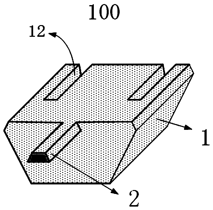
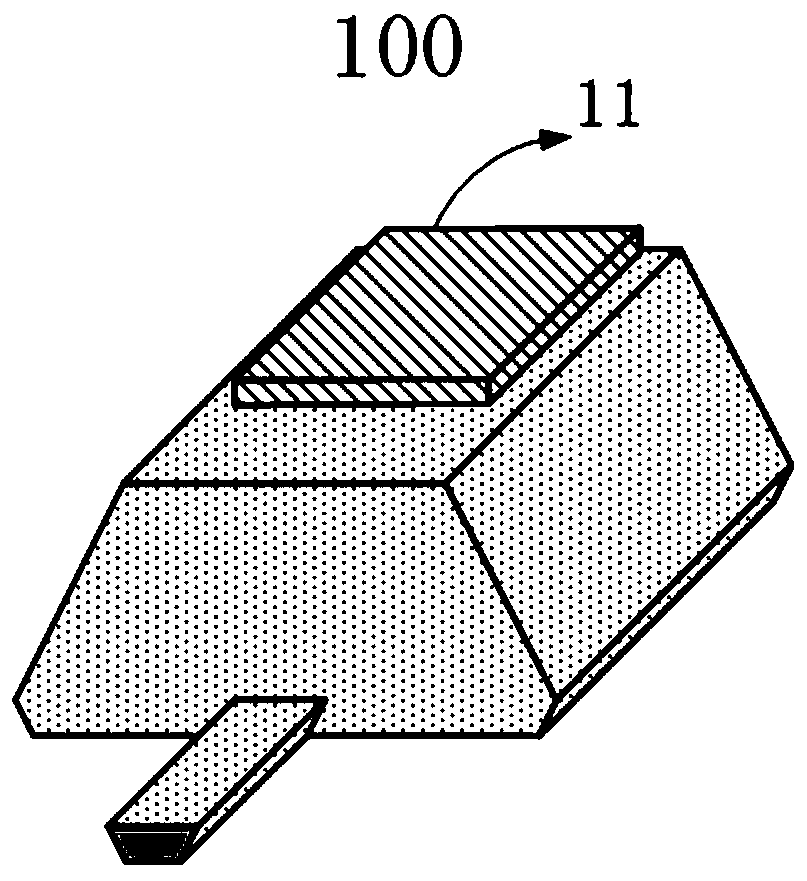
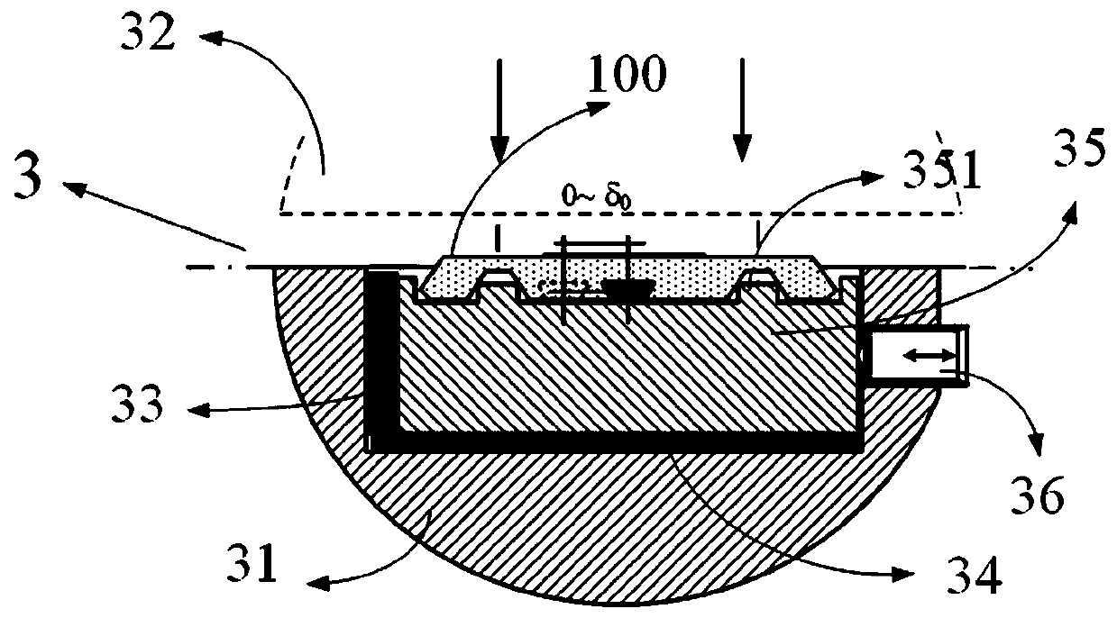
Micro single crystal silicon tool electrode for electrolytic machining and preparation method thereof
A tool electrode, single crystal silicon technology, applied in machining electrodes, electric machining equipment, electrode manufacturing and other directions, can solve the problems of large thermal expansion coefficient gap, short service life, weak metal adhesion, etc. Reduced size and high hardness
- Summary
- Abstract
- Description
- Claims
- Application Information
AI Technical Summary
Problems solved by technology
Method used
Image
Examples
preparation example Construction
[0037] see Figure 5 , the present invention provides a kind of preparation method of micro single crystal silicon tool electrode for electrolytic processing, it comprises the following steps:
[0038] S1, providing a single crystal silicon substrate, the substrate has an upper surface and a lower surface opposite to each other;
[0039] S2, preparing a protective layer on the upper and lower surfaces of the substrate as a mask window for the etching process, the mask window including the tool electrode profile and the back thinning window;
[0040] S3, etching the substrate to form a patterned micro-single crystal silicon tool electrode profile for electrolytic machining;
[0041] S4, completely removing the protective layer on the upper and lower surfaces of the substrate;
[0042] S5, depositing an insulating layer on all surfaces of the substrate;
[0043] S6, preparing a layer of patterned protective layer on the insulating layer, removing the partial insulating layer ...
Embodiment 1
[0049] see Figure 6 , in step S1, the single crystal silicon substrate 13 is selected from a highly doped N-type or P-type silicon wafer, preferably an N-type silicon wafer. Its doping concentration needs to be 10 16 ~10 20 / cm 2 range, preferably 10 19 ~10 20 / cm 2 range, more preferably 10 20 / cm 2 . Its resistivity is preferably 10 -3 Ω·cm. The (100) crystal face of the silicon wafer is selected, and the silicon wafer is polished on both sides. In this embodiment, the N-type silicon wafer with (100) crystal plane doped at a high concentration is selected, the thickness of the silicon wafer is 300 μm, and its resistivity is 10 -3 Ω·cm is a double-sided polished silicon wafer, such as Figure 7 (a) shown.
[0050] In step S2, a layer of silicon dioxide (SiO 2 ), and then a layer of silicon nitride (Si 3 N 4 ), constituting the mask layer 14 to prepare for patterning in the subsequent etching process. In this embodiment, the single crystal silicon substrate 1...
Embodiment 2
[0060] The difference between this embodiment and Embodiment 1 is that in step 1, the single crystal silicon substrate 13 is an undoped (100) crystal plane single crystal silicon wafer, and the thickness of the silicon wafer is 300 μm. The same contour etching process can be carried out, but the Si on the upper and lower surfaces of the single crystal silicon substrate 13 needs to be removed in step 4. 3 N 4 and SiO 2 After complete removal, a doping step of the monocrystalline silicon substrate 13 is added.
[0061] The specific steps are as follows: the monocrystalline silicon substrate 13 is overall doped, and the doping concentration needs to be 10 16 ~10 20 / cm 2 range, preferably 10 19 ~10 20 / cm 2 range, more preferably 10 20 / cm 2 . The doping type is P-type or N-type, preferably N-type. The doping method is thermal diffusion or ion implantation, and the doped impurity is phosphorus (P).
[0062] The micro-silicon single-crystal silicon tool electrode for e...
PUM
| Property | Measurement | Unit |
|---|---|---|
| electrical resistivity | aaaaa | aaaaa |
| electrical resistivity | aaaaa | aaaaa |
| thickness | aaaaa | aaaaa |
Abstract
Description
Claims
Application Information
 - R&D Engineer
- R&D Manager
- IP Professional
- Industry Leading Data Capabilities
- Powerful AI technology
- Patent DNA Extraction
Browse by: Latest US Patents, China's latest patents, Technical Efficacy Thesaurus, Application Domain, Technology Topic, Popular Technical Reports.
© 2024 PatSnap. All rights reserved.Legal|Privacy policy|Modern Slavery Act Transparency Statement|Sitemap|About US| Contact US: help@patsnap.com


