
Fully differential amplifier circuit with high accuracy and high dynamic range

A fully differential amplifier and high dynamic range technology, applied in differential amplifiers, DC-coupled DC amplifiers, amplifiers, etc., can solve the problems of weakening amplifier circuit speed, abnormal working status of tubes, current mirror current mismatch, etc., to achieve It is beneficial to output common mode level, reduce static power consumption, and improve the effect of voltage margin

Pending Publication Date: 2017-01-11
湘潭芯力特电子科技有限公司
View PDF11 Cites 3 Cited by
  • Summary
  • Abstract
  • Description
  • Claims
  • Application Information

AI Technical Summary

Problems solved by technology

However, since Class AB push-pull circuits require floating voltage source biasing, this results in limited voltage margin when combined with traditional folded cascode amplifiers with chopping techniques
In addition, even if each MOS tube is adjusted to the normal working area, due to the relatively limited working range of the tube, it is very susceptible to the influence of voltage spikes caused by chopper switch switching or other factors, such as: cascode current mirror of a tube The drain terminal voltage can only be in the saturation region in a certain limit range. An instantaneous pulse causes the drain terminal voltage of the tube to jump out of this limit range, causing the tube to work abnormally, which in turn causes the current mismatch of the current mirror, and finally reduces the circuit accuracy; Moreover, to restore the working area of ​​the tube to normal, it is limited by the settling time of the amplifier, which indirectly weakens the speed of the entire amplifier circuit.

Method used


Image

  • Fully differential amplifier circuit with high accuracy and high dynamic range
  • Fully differential amplifier circuit with high accuracy and high dynamic range
  • Fully differential amplifier circuit with high accuracy and high dynamic range

Examples


Embodiment Construction

[0028] In order to make the objectives, technical solutions and advantages of the present invention clearer, the embodiments of the present invention will be described in detail below with reference to the accompanying drawings.

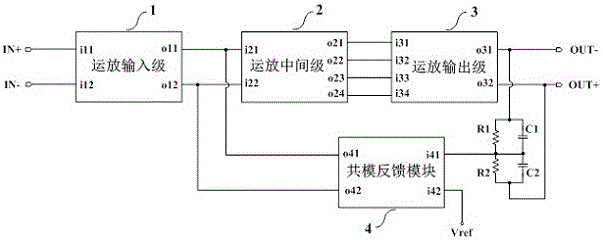
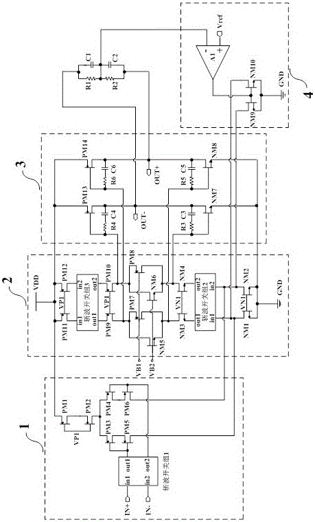
[0029] A fully differential amplifier circuit with high precision and high dynamic range in this embodiment, the overall frame diagram of which is as follows figure 1 As shown, it includes an operational amplifier input stage 1, an operational amplifier intermediate stage 2, an operational amplifier output stage 3, a common mode feedback module 4, a first resistor R1, a second resistor R2, a first capacitor C1, and a second capacitor C2; wherein, The first input terminal and the second input terminal of the operational amplifier input stage 1 are respectively used as the non-inverting input terminal and the inverting input terminal of the operational amplifier input stage, the first output terminal of the operational amplifier input stage 1, and the f...


PUM


Abstract

The invention discloses a fully differential amplifier circuit with high accuracy and a high dynamic range. The overall circuit mainly comprises an operational amplifier input grade, an operational amplifier middle grade, an operational amplifier output grade and a common-mode feedback module and belongs to the field of integrated circuits. In order to improve the accuracy and the dynamic performance of the circuit, the circuit is combined with a folding type cascode operational amplifier structure adopting a chopper technique and an AB type push-pull structure; however, the AB type push-pull circuit requires a floating voltage source to provide static polarization, the cascading number of cascode circuits is increased, and the voltage margin is limited; besides, even if all MOS (metal oxide semiconductor) transistors in the cascode circuits are modulated to the normal work zone, the work sections of the cascode circuits are very limited, and the robustness of the circuit is easily affected by transient pulse and PVT change; the cascode type current source of the cascode grade is changed into a two-transistor self-cascading type current source in order to solve the problem, and the voltage margin of the circuit is improved while the circuit accuracy is guaranteed.

Description

technical field [0001] The invention relates to a full differential amplifier circuit, in particular to a full differential amplifier circuit with high precision and high dynamic range, belonging to the field of integrated circuits. Background technique [0002] The fully differential amplifier circuit is a circuit structure of differential input and differential output. Since the currents of the P-type MOS transistor and the N-type MOS transistor cannot be perfectly matched, it is easy to cause the output common mode level to shift, so the fully differential amplifier needs a common mode. The feedback module is used to stabilize the output common mode level; although the full differential amplifier increases the power consumption compared with the single-ended output amplifier, it improves the common mode rejection ratio (CMRR) and the output voltage swing, which is more suitable for some high precision and high linearity applications. degree of occasion. [0003] Specific...

Claims


Application Information

Patent Timeline
IPC IPC(8): H03F1/02H03F1/26H03F3/45
CPCH03F1/0205H03F1/26H03F3/45179
Inventor 谢亮陆序长张文杰金湘亮
Owner 湘潭芯力特电子科技有限公司
Learn More