
Micro-channel regenerative cooling micro-combustor

A micro-combustion chamber, regenerative cooling technology, applied in the field of aero-engines, to achieve full combustion, improve wall temperature uniformity, and high flameout limit

Active Publication Date: 2017-01-11
XIAMEN UNIV +1
View PDF8 Cites 12 Cited by
  • Summary
  • Abstract
  • Description
  • Claims
  • Application Information

AI Technical Summary

Problems solved by technology

[0005] In order to solve the above-mentioned problems existing in the prior art, the present invention provides a combustor structure that uses microchannels to realize regenerative cooling. Regenerative cooling is to use fuel as a coolant at the same time, and use the fuel to absorb the heat released by the combustor and heat it to a certain level. temperature, thereby cracking into small molecular flammable substances, entering the combustion chamber for further combustion, and releasing the absorbed heat to the combustion chamber, while improving the combustion efficiency and realizing the cooling of the wall of the combustion chamber. The micro-scale effect strengthens the advantages of heat transfer, improves the heat transfer effect of fuel oil, reduces the wall temperature and temperature gradient of the combustion chamber, and thus solves the problem of excessive thermal stress, and realizes effective thermal protection of the combustion chamber

Method used


Image

  • Micro-channel regenerative cooling micro-combustor
  • Micro-channel regenerative cooling micro-combustor
  • Micro-channel regenerative cooling micro-combustor

Examples


Embodiment Construction

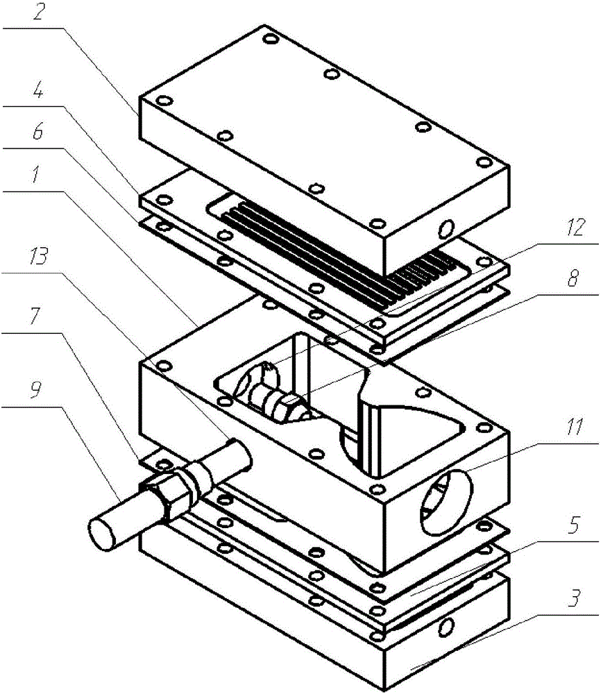
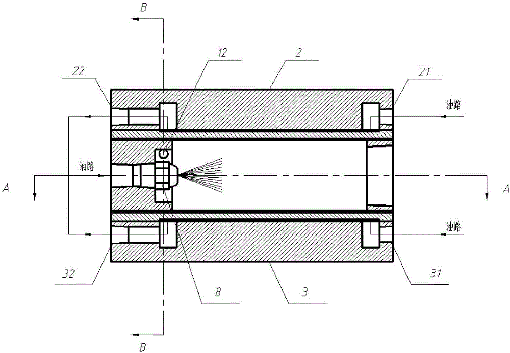
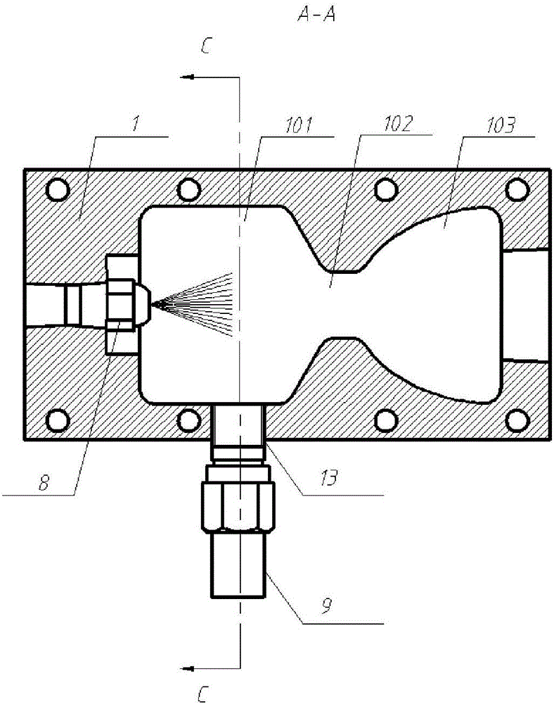
[0024] see figure 1 and figure 2 , a micro-combustor with micro-channel regenerative cooling, such as figure 1 As shown, it is composed of the combustion chamber (1) and the intermediate backing plates (6, 7) on the upper and lower sides, the microchannel plate (4, 5), and the top cover plate (2, 3) by stacking and combining , the combustion chamber (1), the middle backing plate (6, 7), and the microchannel plate (4, 5) form a closed combustion chamber, the front end of the combustion chamber (1) is provided with a fuel nozzle (8), and the rear end is exhaust gas The discharge port (11), the air inlet (12) is provided on one side of the wall, and the connection port (13) of the igniter (9) is provided on the other side; the front and rear ends of the top cover plates (2, 3) are respectively provided with fuel inlets (21, 31) and outlets (22, 32); the microchannel plate (4, 5) comprises 10-20 microchannels (41) arranged in parallel and equally spaced. During assembly, the t...


PUM

PropertyMeasurementUnit
Center distanceaaaaaaaaaa
Hydraulic diameteraaaaaaaaaa
Vertical widthaaaaaaaaaa

Abstract

The invention discloses a micro-channel regenerative cooling micro-combustor. By the aid of a combustion cavity body, a middle base plate, a micro-channel plate and a top cover plate, the combustion cavity, the middle base plate and the micro-channel plate form a closed combustion cavity, wherein the middle base plate, the micro-channel plate and the top cover plate are sequentially arranged on the upper side and the lower side of the combustion cavity in a laminated manner. Fuel oil flows through the micro-channel plate and then is sprayed into the combustion cavity body through a fuel oil atomizing nozzle, the fuel oil is ignited after mixed with air entering an air inlet, the fuel oil simultaneously serves as a coolant, heat released by the combustor is absorbed by a micro-channel, and the wall of the combustor is cooled while combustion efficiency is improved, so that regenerative cooling is realized. By taking the advantages of large surface area and micro-size effect enhanced heat exchange of the micro-channel, the wall temperature and the temperature gradient of the combustor are reduced, the problem of excessive heat stress is solved, and effective heat protection of the combustor is realized. Besides, preheated fuels are cracked, ignition performance is improved, and extinction limit and combustion efficiency are increased.

Description

technical field [0001] The invention relates to the field of aero-engines, in particular to a micro-combustion chamber for micro-channel regenerative cooling. Background technique [0002] With the improvement of the thrust-to-weight ratio of aviation gas turbine engines, the design of combustion chambers is developing in the direction of high temperature rise and high heat capacity. As a place for tissue combustion, the combustion chamber works in a high-temperature and high-pressure environment for a long time, and it has to bear great thermal stress, creep stress and fatigue stress. Its life and reliability become the key to determine the life and reliability of the engine. Combustion chambers are generally made of high-temperature resistant alloys, but the current temperature resistance of metal materials is below 1000 degrees Celsius, which is far lower than the temperature of gas; and the temperature resistance of metal materials is much lower than that of gas temperat...

Claims


Application Information

Patent Timeline
IPC IPC(8): F23R3/58
CPCF23R3/58
Inventor 邓大祥谢炎林万伟黄青松陈小龙付沁林
Owner XIAMEN UNIV
Learn More