
Condensed-phase combustion product collecting device controlling constant pressure through spring force

A technology of combustion products and collection devices, which is used in chemical analysis by combustion, sampling devices, etc., can solve problems such as insufficient pressure in the collection container, and achieve the effects of simple structure, convenient collection and small volume

Inactive Publication Date: 2017-01-04
NORTHWESTERN POLYTECHNICAL UNIV
View PDF7 Cites 10 Cited by
  • Summary
  • Abstract
  • Description
  • Claims
  • Application Information

AI Technical Summary

Problems solved by technology

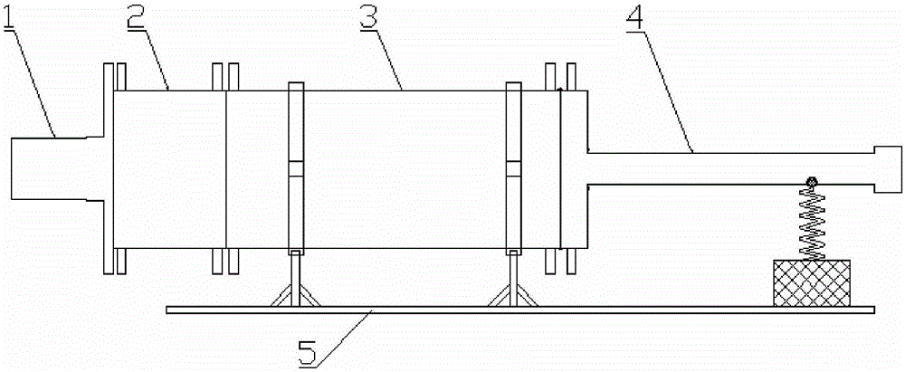
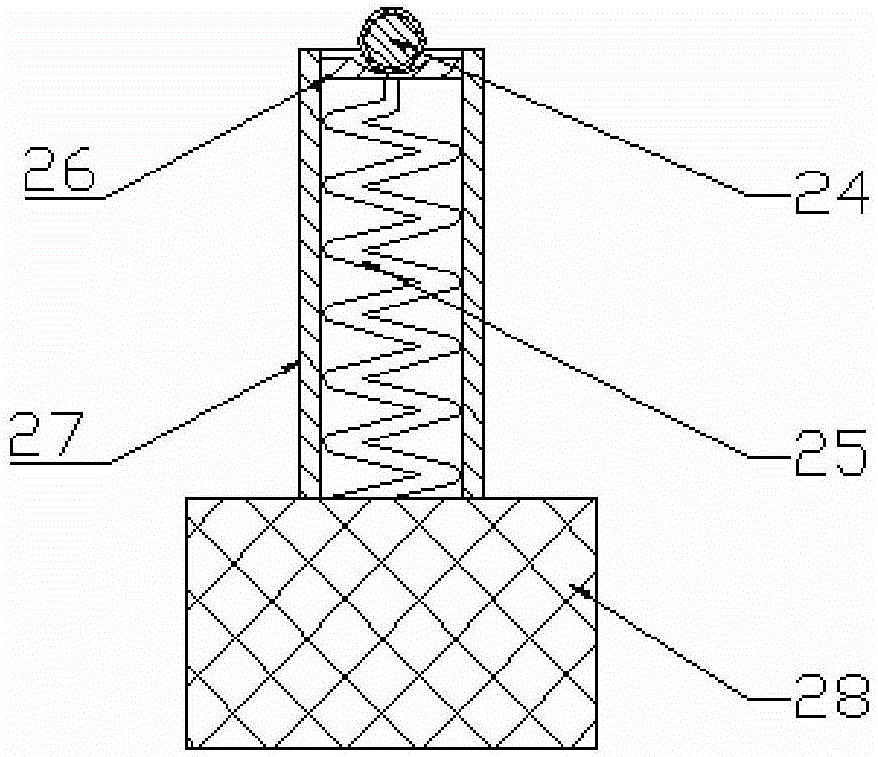
[0007] In order to overcome the problem that the pressure of the collection container in the existing device is not stable enough and avoid the chemical reaction between water and condensed phase combustion products, the present invention proposes a collection device for condensed phase combustion products that uses spring force to control constant pressure; Automatic pressure relief, simulating the stable pressure environment in the engine combustion chamber, and realizing the pollution-free collection of all condensed phase combustion products in the engine combustion chamber

Method used


Image

  • Condensed-phase combustion product collecting device controlling constant pressure through spring force
  • Condensed-phase combustion product collecting device controlling constant pressure through spring force
  • Condensed-phase combustion product collecting device controlling constant pressure through spring force

Examples


Embodiment 1

[0050] The propellant bracket 6, propellant 7, and propellant bracket 8 are sequentially assembled in the combustion chamber 1, and the propellant combustion end face is 80 mm away from the combustion product collection box body. According to the above-mentioned specific operation steps, the collection of condensed phase combustion products under the condition of flow distance of 80 mm and experimental working pressure of 5 MPa is completed. Using a laser particle size analyzer Mastersizer 2000, Malvern carried out particle size analysis on the collected condensed phase combustion products, and obtained Image 6 The particle size distribution diagram is shown. Under the experimental conditions of a flow distance of 80 mm and a working pressure of 5 MPa, the particle size distribution of the condensed phase combustion products has two obvious peaks, which are the low particle size region of 0.25-1.3 μm and the medium particle size region of 1.3-30 μm. The third section of the c...

Embodiment 2

[0052] In the combustion chamber 1, the propellant bracket 6, the graphite spacer 29, the propellant 7, and the propellant support 8 are sequentially assembled. The graphite spacer pushes the propellant forward by 40 mm, and the combustion end face of the propellant is separated from the combustion product collection box body 40mm. Follow the specific operation steps to complete the collection of condensed phase combustion products under the conditions of a flow distance of 40 mm and an experimental working pressure of 5 MPa. Using a laser particle size analyzer Mastersizer 2000, Malvern carried out particle size analysis on the collected condensed phase combustion products, and obtained Figure 7 The particle size distribution diagram is shown. Under the experimental conditions of a flow distance of 40 mm and a working pressure of 5 MPa, the particle size distribution of the condensed phase combustion product, that is, the 2# sample, has two obvious peaks, which are the low ...

Embodiment 3

[0054] The propellant bracket 6, propellant 7, and propellant support 8 are sequentially assembled in the combustion chamber, and the propellant combustion end face is 80 mm away from the combustion product collection box body. Then, according to the above-mentioned specific operation steps, the collection of condensed phase combustion products under the conditions of a flow distance of 80 mm and an experimental working pressure of 7 MPa is completed. Using a laser particle size analyzer Mastersizer 2000, Malvern carried out particle size analysis on the collected condensed phase combustion products, and obtained Figure 8 The particle size distribution diagram is shown. Under the experimental conditions of a flow distance of 80 mm and a working pressure of 7 MPa, the particle size distribution of the condensed phase combustion product, that is, the 3# sample, has three obvious peaks, which are the low particle size region 0.25-1.3 μm, the medium particle size region 1.3-16 μm...


PUM

PropertyMeasurementUnit
particle diameteraaaaaaaaaa
thicknessaaaaaaaaaa

Abstract

The invention discloses a condensed-phase combustion product collecting device controlling constant pressure through spring force. A stable pressure environment in an engine combustion chamber is simulated through automatic pressure relief of spring force, and therefore pollution-free collection on all condensed-phase combustion products in the engine combustion chamber is achieved. The volume of the collecting device is regulated through movement of a piston to regulate pressure of the two sides of the piston; air is exhausted outwards through a steel ball and a spring mechanism which are arranged at an exhaust port of a tail cavity pipe, therefore, the pressure of the two sides of the piston achieves a balanced state, and a stable and balanced pressure environment which is kept under test-specified pressure is established. By arranging a fluororubber seal ring in a groove formed in the ring surface of the piston, sealing of space of the two sides of the piston is achieved, and it is guaranteed that the condensed-phase combustion products are not polluted; the steel ball is coated with a silicone rubber layer, so that the leakproofness of the steel ball and the spring mechanism is guaranteed. The length of a propellant support in the engine combustion chamber is regulated as needed, and therefore the condensed-phase combustion product can be conveniently collected under the conditions of different flow distances. The collecting device is simple in structure, small in size and easy to machine.

Description

technical field [0001] The invention relates to the technical field of solid rocket motors, in particular to a device for collecting condensed phase combustion products using spring force to control constant pressure. Background technique [0002] In solid propellants, metal fuels with higher combustion calorific value, such as aluminum powder, are usually added to increase the specific impulse of the solid propellant. For high aluminum-containing composite propellants, due to the high temperature in the combustion chamber, the metal combustion product Al 2 o 3 It is in a molten state in the gas, that is, condensed phase particles. The particle size and distribution of condensed phase combustion products are important parameters for engine performance analysis and work process simulation, such as the analysis of the law of two-phase flow in solid rocket motors, the mechanical erosion of condensed phase products on the engine insulation layer and nozzle, and the impact of c...

Claims


Application Information

Patent Timeline
Patent Type & Authority Applications(China)
IPC IPC(8): G01N1/10G01N31/12
CPCG01N1/10G01N31/12
Inventor 胡松启刘元敏张研刘林林刘凌毅
Owner NORTHWESTERN POLYTECHNICAL UNIV
Learn More