
Anti-high-impact S-shaped elastic beam MEMS (Micro-electromechanical Systems) annular vibratory gyroscope harmonic oscillator structure

A technology of vibrating gyroscope and elastic beam, which is applied in the direction of gyroscopic effect for speed measurement, gyroscope/steering sensing device, speed/acceleration/shock measurement, etc., which can solve the problems of poor shock resistance of MEMS vibrating gyroscope and achieve resonance frequency matching. Easy, clever design, to achieve the effect of natural matching of damping

Active Publication Date: 2017-01-04
ZHONGBEI UNIV
View PDF1 Cites 10 Cited by
  • Summary
  • Abstract
  • Description
  • Claims
  • Application Information

AI Technical Summary

Problems solved by technology

[0003] In order to solve the problem of poor impact resistance of the existing MEMS vibrating gyroscope, the present invention provides a resonator structure of an S-shaped elastic beam MEMS ring vibrating gyroscope with high impact resistance

Method used


Image

  • Anti-high-impact S-shaped elastic beam MEMS (Micro-electromechanical Systems) annular vibratory gyroscope harmonic oscillator structure
  • Anti-high-impact S-shaped elastic beam MEMS (Micro-electromechanical Systems) annular vibratory gyroscope harmonic oscillator structure
  • Anti-high-impact S-shaped elastic beam MEMS (Micro-electromechanical Systems) annular vibratory gyroscope harmonic oscillator structure

Examples


Embodiment Construction

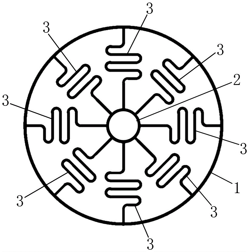
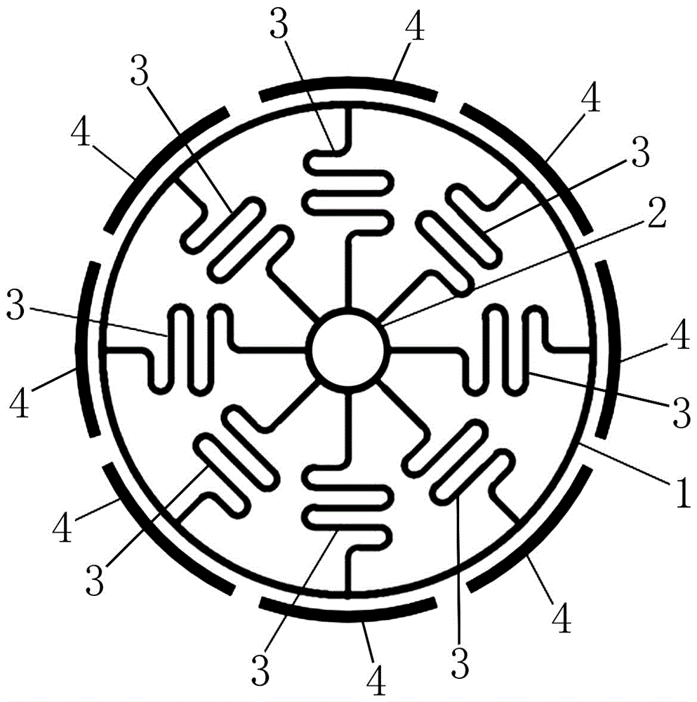
[0017] A high-impact S-shaped elastic beam MEMS ring vibration gyro resonator structure, including a ring-shaped resonant mass 1, a cylindrical central anchor point 2, and a spoke-shaped elastic support suspension beam 3;

[0018] Among them, the cylindrical central anchor point 2 is located in the inner cavity of the annular resonant mass 1, and the axis of the cylindrical central anchor point 2 coincides with the axis of the annular resonant mass 1; the number of spoke-shaped elastic support suspension beams 3 is eight , and eight spoke-shaped elastic support suspension beams 3 are equidistantly arranged around the axis of the cylindrical central anchor point 2;

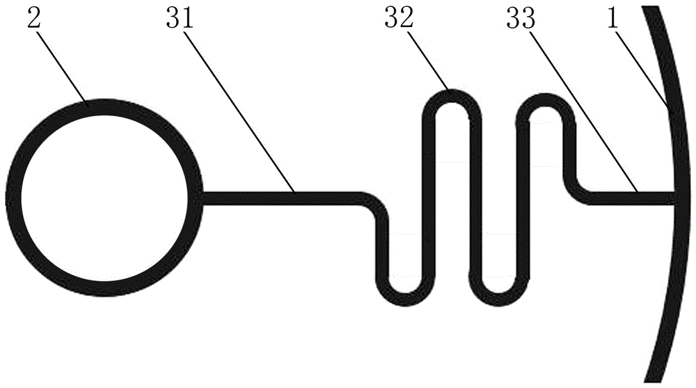
[0019] Each spoke shape elastic support suspension beam 3 is all made of the first sheet elastic support suspension beam 31, S-shaped elastic support suspension beam 32, and the second sheet elastic support suspension beam 33; The outer surface of the central anchor point 2 is fixed; the tail end of the S-shaped el...


PUM


Abstract

The invention relates to an MEMS (Micro-electromechanical Systems) annular vibratory gyroscope and in particular relates to an anti-high-impact S-shaped elastic beam MEMS annular vibratory gyroscope harmonic oscillator structure, aiming at solving the problem that the anti-impact performance of an existing MEMS vibratory gyroscope is poor. The anti-high-impact S-shaped elastic beam MEMS annular vibratory gyroscope harmonic oscillator structure comprises an annular resonance oscillation mass, a cylindrical central anchor point and spoke-shaped elastic supporting suspension arms, wherein the cylindrical central anchor point is located at an inner cavity of the annular resonance oscillation mass; the axis of the cylindrical central anchor point is overlapped with the axis of the annular resonance oscillation mass; eight spoke-shaped elastic supporting suspension arms are arranged; the eight spoke-shaped elastic supporting suspension arms are arrayed at equal distance around the axis of the cylindrical central anchor point; each spoke-shaped elastic supporting suspension arm is composed of a firs sheet-shaped elastic supporting suspension arm, an S-shaped elastic supporting suspension arm and a second sheet-shaped elastic supporting suspension arm. The anti-high-impact S-shaped elastic beam MEMS annular vibratory gyroscope harmonic oscillator structure is applicable to the fields of weapon guidance, aerospace, automobile industry, biomedicine, consumer electronics and the like.

Description

technical field [0001] The invention relates to a MEMS vibrating gyroscope, in particular to a high-impact S-shaped elastic beam MEMS ring vibrating gyroscope resonator structure. Background technique [0002] MEMS vibrating gyroscope is an inertial sensing device based on the Coriolis effect, which can detect the angle or angular velocity of a rotating object. MEMS vibrating gyroscope has the advantages of small size, light weight, low power consumption, mass production, and low price. It can be widely used in weapon guidance, aerospace, automotive industry, biomedicine, consumer electronics and other fields, and has extremely broad application prospects. . The working principle of the MEMS vibrating gyroscope is as follows: The MEMS vibrating gyroscope has two inherent four-antinode bending vibration modes with the same resonant frequency, and one of the bending vibration modes can be used as the driving mode, and the other bending vibration mode can be used as the drivin...

Claims


Application Information

Patent Timeline
IPC IPC(8): G01C19/5684
CPCG01C19/5684
Inventor 刘俊寇志伟曹慧亮石云波连树仁冯恒振唐军
Owner ZHONGBEI UNIV
Learn More