Polisher for workpiece flange burrs and polishing process thereof
A technology for grinding machines and workpieces, which is applied to machine tools, grinding racks, grinding machines, etc. suitable for grinding the edge of workpieces, and can solve the problems of poor versatility of grinding devices, operators are susceptible to dust damage, and poor grinding efficiency, etc., to achieve Improve service life, low production cost, good grinding effect
- Summary
- Abstract
- Description
- Claims
- Application Information
AI Technical Summary
Problems solved by technology
Method used
Image
Examples
Embodiment 1
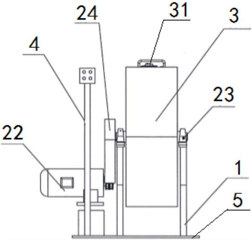
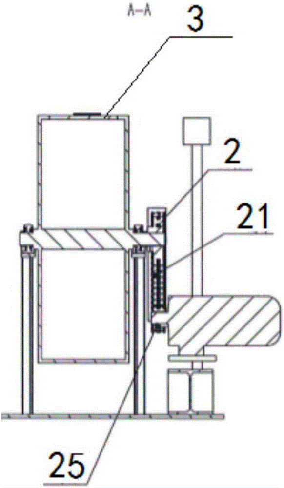
[0042] A kind of mutual grinding machine for workpiece flash and burr in this embodiment, such as figure 1 , 2 , 4, including a support 1, a transmission mechanism 2 and a chassis 5, and also includes a self-polishing box 3, wherein: the support 1 is two plate structures vertically fixed on the chassis 5, which can be a square iron plate, so The self-grinding box 3 is mounted in the middle of the support 1 through a rotating shaft, and is rotatably connected with the support 1 , and the transmission mechanism 2 provides rotational power for the rotating shaft of the self-polishing box 3 . This mutual grinding machine can grind off the respective burrs through the mutual grinding of the workpieces themselves, making full use of the irregularity of different workpieces in the position and body position of the self-grinding box after the self-grinding box rotates at a specific speed , Grinding the flash of the workpiece in an all-round way with no difference, without special gri...
Embodiment 2
[0044] A workpiece flash and burr mutual grinding machine of this embodiment has the same basic structure as that of embodiment 1, and the improvement is that the plate structure of the bracket 1 is two triangular plates, triangular, and the structure is stable, so as to ensure the self-grinding of the box body. Stable rotation improves the service life of the entire equipment. The self-polishing box 3 has a pentagonal cross-section and a diameter of 1.2m; the transmission mechanism 2 includes a transmission belt 21, a motor 22, a bearing 23 and a driving wheel 25; there are two bearings 23, which are fixed on two triangular plates The top of the self-grinding box 3 is fixed by the sleeve socket of the central shaft of the self-polishing box 3 and two bearings 23; The rotation speed of the whole device can be realized through the adjustment of the motor frequency, and the grinding of the flash of workpieces with different specifications can be realized by adjusting the rotatio...
Embodiment 3
[0052] A workpiece flash and burr mutual grinding machine of this embodiment has the same basic structure as that of Embodiment 2, and the improvement and difference are that a belt transmission shield 24 is fixed on the periphery of the transmission belt 21, which not only protects the chain, but also reduces work-related injuries. risk; the rotating shaft of the self-polishing box 3 is an eccentric shaft, so that when the rotating speed is too fast, the positions of the workpieces in the self-polishing box remain relatively stationary to reduce the grinding efficiency, and the rotating speed is too fast, and the centrifugal force generated is too large It is also easy to cause mutual damage to the workpieces. The box section of the self-polishing box 3 is octagonal.
[0053] A grinding process of a workpiece flash and burr mutual grinding machine in this embodiment, the steps are:
[0054] Step 1, feeding: open the feed port cover 31, pour 200 kilograms of iron workpieces w...
PUM
 Abstract
Description
Claims
Application Information
 - R&D
- Intellectual Property
- Life Sciences
- Materials
- Tech Scout
- Unparalleled Data Quality
- Higher Quality Content
- 60% Fewer Hallucinations
Browse by: Latest US Patents, China's latest patents, Technical Efficacy Thesaurus, Application Domain, Technology Topic, Popular Technical Reports.
© 2025 PatSnap. All rights reserved.Legal|Privacy policy|Modern Slavery Act Transparency Statement|Sitemap|About US| Contact US: help@patsnap.com


