
Self repair device and method thereof

A self-repair, device technology, applied in the field of integrated circuits, can solve problems such as column faults that cannot be repaired

Active Publication Date: 2016-12-28
SK HYNIX INC
View PDF6 Cites 35 Cited by
  • Summary
  • Abstract
  • Description
  • Claims
  • Application Information

AI Technical Summary

Problems solved by technology

Therefore, bit faults and row faults can be repaired, but column faults cannot
[0014] Also, in order to increase the yield, the testing process must be repeated several times

Method used


Image

  • Self repair device and method thereof
  • Self repair device and method thereof
  • Self repair device and method thereof

Examples


Embodiment Construction

[0025] Hereinafter, a self-healing device and method will be described below through various examples of embodiments with reference to the accompanying drawings.

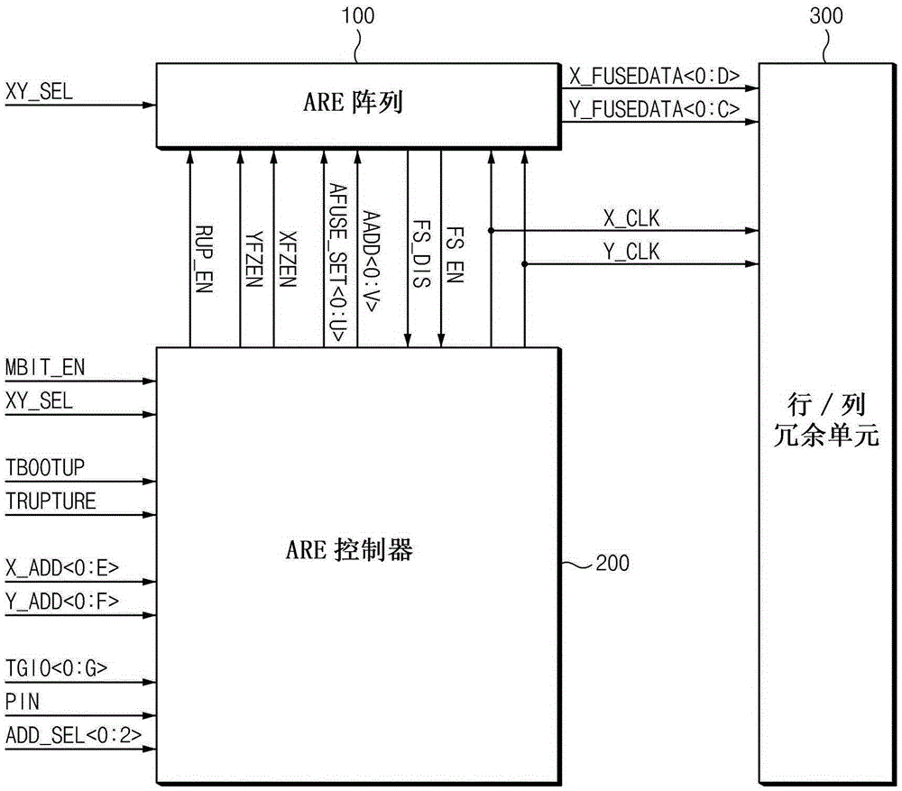
[0026] figure 1 is a configuration diagram of a self-healing device according to an embodiment. In one embodiment, a semiconductor memory device may include a self-healing device.

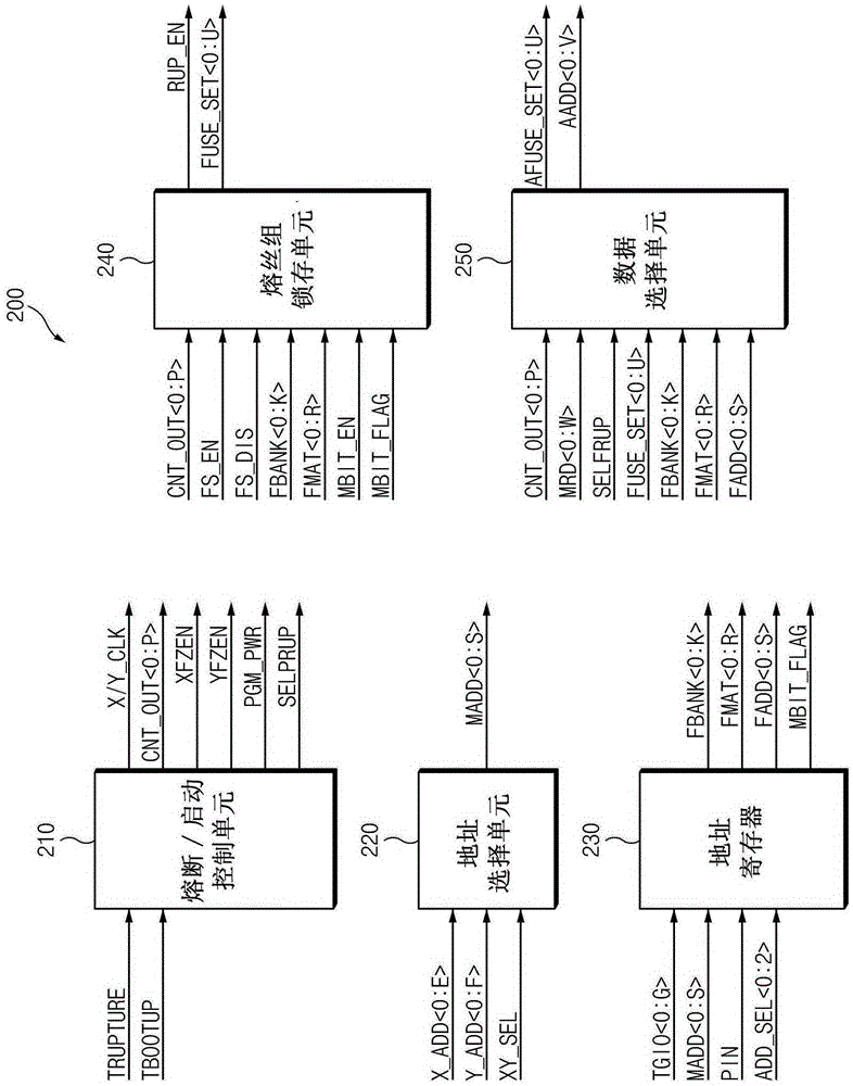
[0027] A self-healing device according to an embodiment may include an Array Rupture Electrical fuse (hereinafter referred to as “ARE”) array 100 , an ARE controller 200 and a row / column redundancy unit 300 .

[0028] ARE array 100 may store information about addresses that have failed. Such information collected during a memory test may be temporarily stored in a storage device of a memory tester, and then applied to a semiconductor memory device to blow an electric fuse corresponding to a corresponding address to permanently store the information in in semiconductor memory devices.

[0029] ARE array 100 can receive fuse set select...


PUM


Abstract

A self repair device may include: an electrical fuse array configured to store bit information of a failed address in a fuse; an electrical fuse controller configured to store a row address or column address corresponding to a failed bit when a failure occurs, generate a repair address by comparing a failed address inputted during a test to the address stored therein, output a rupture enable signal for controlling a rupture operation of the electrical fuse array, and output row fuse set data or column fuse set data in response to the failed address; and a row / column redundancy unit configured to perform a row redundancy or column redundancy operation in response to the row fuse set data or the column fuse set data applied from the electrical fuse array.

Description

[0001] Cross References to Related Applications [0002] This application claims priority from Korean Patent Application No. 10-2015-0085296 filed with the Korean Intellectual Property Office on June 16, 2015, the entire contents of which are hereby incorporated by reference. technical field [0003] Various embodiments relate generally to integrated circuits and, more particularly, to self-healing devices and methods for improving repair efficiency during package repair operations. Background technique [0004] A semiconductor memory such as a dynamic random access memory (hereinafter referred to as "DRAM") includes a plurality of memory cells arranged in a matrix. The demand for highly integrated semiconductor memory devices is leading to a reduction in design rules, which define the minimum feature size for chip lithography. A reduction in design rules may increase the probability of defects in a semiconductor memory device, and one or more defects in a chip may result i...

Claims


Application Information

Patent Timeline
Patent Type & Authority Applications(China)
IPC IPC(8): G11C29/44G11C17/16
CPCG11C17/16G11C29/4401G11C29/78G11C29/787G11C2029/4402G11C17/18G11C29/76
Inventor 沈荣辅
Owner SK HYNIX INC
Learn More