
Microcurrent detecting system in dielectric medium insulation diagnosis

A detection system, micro-current technology, applied in the direction of only measuring current, measuring current/voltage, measuring device, etc., can solve problems such as inconvenience in testing

Inactive Publication Date: 2016-12-07
HARBIN UNIV OF SCI & TECH
View PDF0 Cites 4 Cited by
  • Summary
  • Abstract
  • Description
  • Claims
  • Application Information

AI Technical Summary

Problems solved by technology

[0005] Sampling resistance differential detection method, the sampling resistance differential detection method has the advantages of simple structure and can effectively remove common-mode interference, but the sampling resistance and the capacitive sample are connected in series in the circuit, and the results need to be further converted when measuring the loss curve, which brings new problems to the test. inconvenient
[0006] The above methods all have obvious shortcomings. In order to make up for the shortcomings of the existing measurement methods, a new micro-current detection circuit is proposed.

Method used


Image

  • Microcurrent detecting system in dielectric medium insulation diagnosis
  • Microcurrent detecting system in dielectric medium insulation diagnosis
  • Microcurrent detecting system in dielectric medium insulation diagnosis

Examples


specific Embodiment approach

[0017] Specific embodiments: In order to describe the technical features of this solution in detail, the patent of the present invention will be described in detail below through specific embodiments and in conjunction with the accompanying drawings.

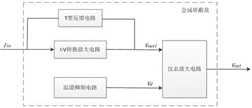
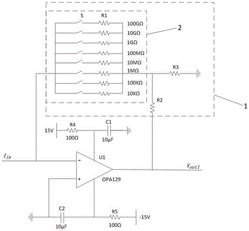
[0018] as attached figure 1 As shown, a micro-current detection system includes an I-V conversion amplifier circuit, a temperature drift suppression circuit, an instrument amplifier circuit and a power filter circuit, and a metal shielding box is set for the above circuit and grounded. The output of the I-V conversion amplifier circuit and the output of the temperature drift suppression circuit are connected as the input of the instrument amplifier circuit. The power filter circuit provides stable power for active devices such as operational amplifiers in the module. The grounded metal shielding box shields external electromagnetic interference. .

[0019] The I-V conversion amplifying circuit is used as a primary amplifying ci...


PUM


Abstract

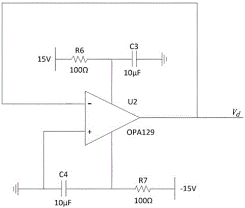
The invention discloses a microcurrent detecting system in dielectric medium insulation diagnosis. The system comprises an I-V conversion amplifying circuit, a temperature drift inhibiting circuit, an instrument amplifying circuit and a power source filter circuit, and a grounded metal shielding box is arranged for the circuit. The microcurrent detecting system is characterized in that microcurrent is converted into voltage through the I-V conversion amplifying circuit and subjected to primary amplifying, the microcurrent is further amplified through the instrument amplifying circuit and output, the temperature drift inhibiting circuit offsets temperature drift of an operational amplifier in the I-V conversion circuit, the detecting precision is improved, the influence of power source fluctuation and harmonic waves on the detecting precision can be reduced through the power source filter circuit, and the influence of the external electromagnetic environment can be reduced through the grounded metal shielding box. The I-V conversion amplifying circuit comprises a T type feedback circuit and a range changing switching circuit, and therefore input impedance is increased, and the detecting range is widened. According to the module, the microcurrent detecting precision is high, and the detecting range is wide. The system has high application value.

Description

technical field [0001] The patent of the present invention relates to a micro-current detection system used in dielectric insulation detection. Background technique [0002] In dielectric insulation detection, it is necessary to apply a high voltage to the dielectric, then detect the weak current flowing in the dielectric, and analyze the current in the frequency domain or time domain. Since the current is often in the microampere or picoampere level, it is extremely important to detect and amplify the microcurrent without distortion. At present, there are mainly methods for microcurrent detection. [0003] The large resistor negative feedback detection method makes a weak current flow through a resistor with a large resistance value, thereby generating a measurable voltage at both ends of the resistor to realize micro-current detection. However, this method has too high a requirement on the accuracy of the resistance, and the greater the resistance, the worse the stability...

Claims


Application Information

Patent Timeline
IPC IPC(8): G01R19/00G01R31/14
CPCG01R19/0092G01R31/14
Inventor 魏新劳孙槐胡玉柱
Owner HARBIN UNIV OF SCI & TECH
Learn More