
A Radial Piezoelectric Actuator Based on Flexible Amplified Structure

A piezoelectric driver, flexible technology, applied in the direction of piezoelectric effect/electrostrictive or magnetostrictive motors, generators/motors, electrical components, etc., can solve the problem of a single output direction of the driver, and improve the radial output Displacement range, simple design and compact structure

Active Publication Date: 2018-10-30
XI AN JIAOTONG UNIV
View PDF6 Cites 0 Cited by
  • Summary
  • Abstract
  • Description
  • Claims
  • Application Information

AI Technical Summary

Problems solved by technology

[0005] The purpose of the present invention is to provide a radial piezoelectric driver based on a flexible amplifying structure, which is used to solve the problem of how to realize multi-directional output while realizing displacement amplification. The present invention uses a piezoelectric driver as a power source and has a Nanoscale precision, large output force, sub-millisecond response, compact structure and high lateral rigidity, etc., and realize radial displacement output at the same time, which solves the problem of a single output direction of the driver

Method used


Image

  • A Radial Piezoelectric Actuator Based on Flexible Amplified Structure
  • A Radial Piezoelectric Actuator Based on Flexible Amplified Structure
  • A Radial Piezoelectric Actuator Based on Flexible Amplified Structure

Examples


Embodiment 1

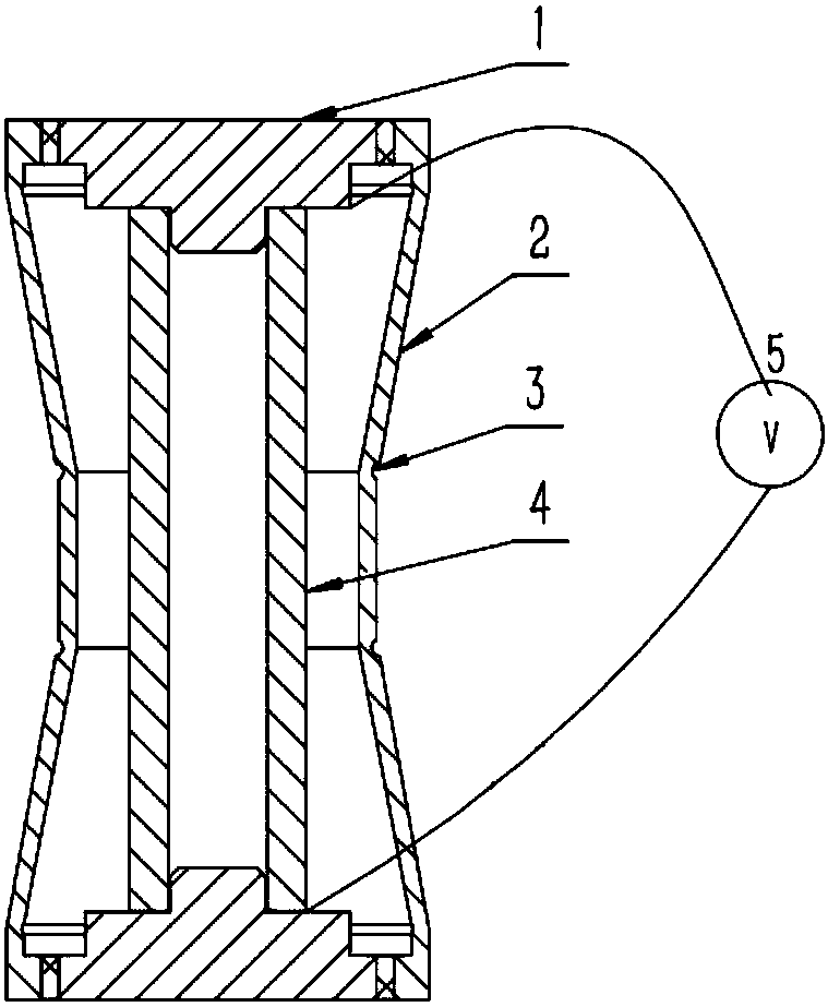
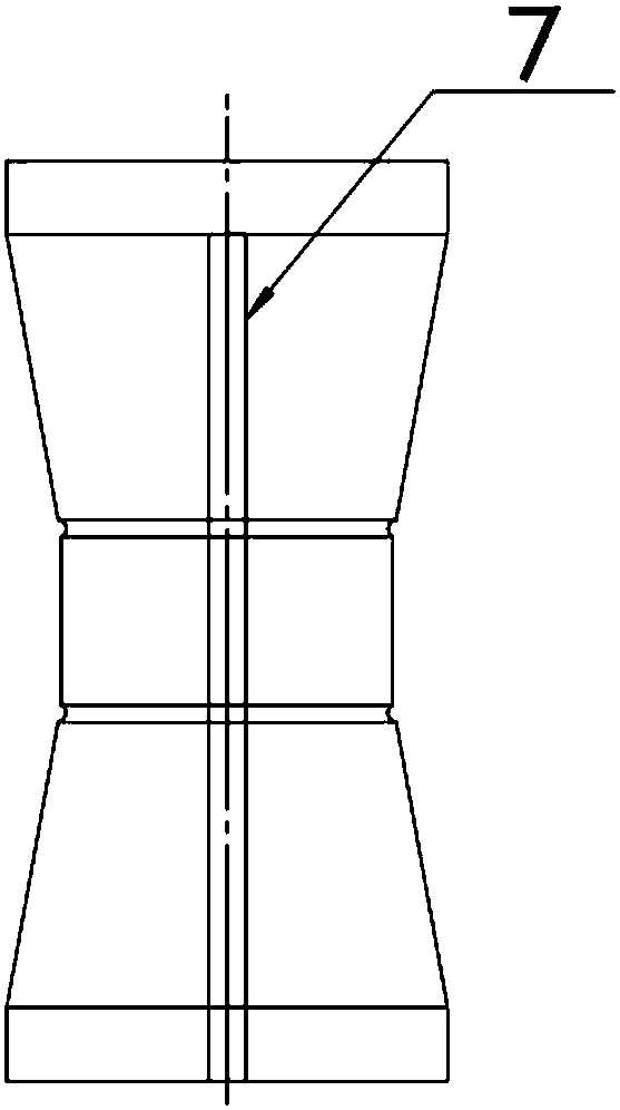
[0042] First, the lower end cover 1 is screwed into the bottom of the sleeve 2, and connected through internal and external threads; the small diameter end of the lower end cover 1 is embedded in the inner side of the piezoelectric stack drive unit 4, and the lower surface of the piezoelectric stack drive unit 4 is connected to the inner surface of the piezoelectric stack drive unit 4. The stepped surface of the lower end cover 1 is in contact; the power line of the piezoelectric stack drive unit 4 is led out from the expansion joint 7 on the side wall of the sleeve 2, and the drive power 5 is applied; the small diameter end of the upper end cover 1 is embedded in the piezoelectric stack drive unit 4 Inside, the stepped surface of the upper end cover 1 is in contact with the upper surface of the piezoelectric stack drive unit 4; the large diameter end of the upper end cover 1 has an external thread, and the top of the sleeve 3 has an internal thread, and the end cover 1 is screw...

Embodiment 2

[0044] The difference from Embodiment 1 is that in this embodiment, the end cap 1 and the sleeve 3 do not have external threads and internal threads, and the end cap 1 and the sleeve 2 are fixed by fastening screws 6; the small diameter ends of the upper and lower end caps 1 There is a groove, and the piezoelectric stack driving unit 4 is placed in the groove, and the two ends of the piezoelectric stack driving unit 4 and the end cover are bonded and fixed by epoxy resin.


PUM


Abstract

The invention discloses a radial piezoelectric driver based on a flexible amplification structure. The radial piezoelectric driver comprises a piezoelectric stacked driving unit, and the outer side of the piezoelectric stacked driving unit is provided with the flexible amplification structure used to amplify the output displacement of the piezoelectric stacked driving unit, and the two ends of the piezoelectric stacked driving unit are connected with a driving power supply disposed on the outer side of the flexible amplification structure by leads. The flexible amplification structure comprises end covers connected with the two ends of the piezoelectric stacked driving unit and a sleeve used to connect the two end covers together. The radial piezoelectric driver adopts the piezoelectric driver as a power source, and has advantages of sub-nanometer level precision, large output force, sub-millisecond level response, compact structure, and high horizontal rigidity, and at the same time, is used to realize the radial displacement output, and is used to solve the problem of the unidirectional output direction of the driver.

Description

technical field [0001] The invention belongs to the field of precision control, and in particular relates to a radial piezoelectric driver based on a flexible amplifying structure. Background technique [0002] In recent years, piezoelectric actuators have been widely used in the field of micro-control due to their fast response speed, low loss, large driving force, wide driving frequency, and high positioning accuracy, such as in the fields of biological and chemical engineering: microsurgery, operation of biological cells , micro-manipulation and other micro-nano positioning platforms, optical engineering field: laser radar system, laser processing micro-operation platform, etc. Although the micro-displacement produced by piezoelectric ceramics is suitable for the field of precision control, its displacement output range is limited and is greatly restricted. Therefore, the piezoelectric actuator mostly adopts a structure based on flexible displacement amplification. The ...

Claims


Application Information

Patent Timeline
Patent Type & Authority Patents(China)
IPC IPC(8): H02N2/04H02N2/02
CPCH02N2/028H02N2/043
Inventor 夏颂杨院
Owner XI AN JIAOTONG UNIV
Learn More