
Synchronous oil separation and cooling device for air compressor

A cooling device and oil separation technology, which is applied to components, separation methods, and dispersed particle separation of elastic fluid pumping devices, can solve problems such as insufficient oil and gas separation, and achieve increased residence time, improved utilization, and Effect of increasing cooling efficiency

Inactive Publication Date: 2016-12-07
四川齐飞新材料科技有限公司
View PDF5 Cites 0 Cited by
  • Summary
  • Abstract
  • Description
  • Claims
  • Application Information

AI Technical Summary

Problems solved by technology

[0004] The technical problem to be solved by the present invention is the problem of insufficient oil and gas separation in the integrated cooler with built-in oil separation device. The purpose is to provide a synchronous oil separation and cooling device for air compressors, which can effectively separate the oil in the compressed gas , and the structure is neat and compact

Method used


Image

  • Synchronous oil separation and cooling device for air compressor
  • Synchronous oil separation and cooling device for air compressor
  • Synchronous oil separation and cooling device for air compressor

Examples


Embodiment

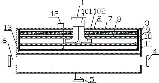
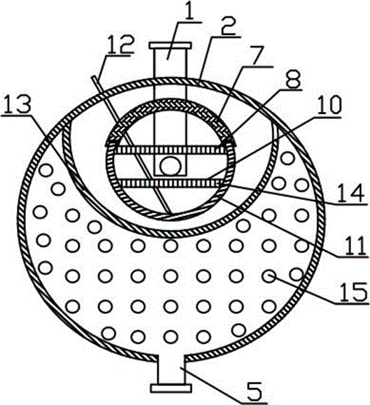
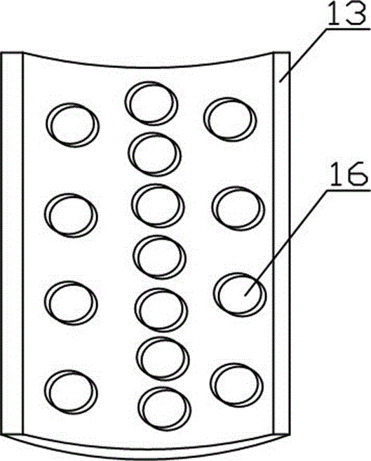
[0031] Such as figure 1 and figure 2 As shown, the present invention is a synchronous oil separation and cooling device for air compressors, including a cylinder body 2, the inner and lower part of the cylinder body 2 is provided with a tube heat exchange tube 14, and the axial ends of the cylinder body 2 are opened through the cover The plate 3 is sealed, and the cover plate 3 can be fixed on the two ports of the cylinder body 2 through flange fixing and sealing. A cooling medium inlet 6 and a cooling medium outlet 4 are provided on the cover plate 3 , an air inlet pipe 1 is provided on the upper part of the cylinder 2 and located at the axial center of the cylinder 2 , and an air outlet 5 is provided on the lower part of the cylinder 2 .

[0032] The barrel 2 also includes an oil storage tank 11 , a baffle 8 , a filter 7 and two support plates 9 . The support plate 9 is welded and fixed on the inner upper part of the cylinder body 2, and is located at two ports in the cyl...


PUM


Abstract

Discloses is a synchronous oil separation and cooling device for an air compressor. The synchronous oil separation and cooling device comprises a barrel. A heat exchange tube is arranged on the lower portion in the barrel. Openings in the two axial ends of the barrel are sealed through cover plates. Each cover plate is provided with a cooling medium inlet and a cooling medium outlet. The barrel is provided with a gas inlet pipe and a gas outlet pipe. The synchronous oil separation and cooling device further comprises an oil storage tank, a baffle plate, a filter and two support plates. The oil storage tank, the baffle plate and the filter are fixed between the two support plates sequentially from bottom to top. The filter is in an arc-shaped plate shape. The arc-shaped edge, axially parallel to the barrel, of the filter is fixed to the oil storage tank in a matched mode. The two edges, axially parallel to the barrel, of the baffle plate are fixed to the oil storage tank. The gas inlet pipe penetrates through the filter and the baffle plate to be led in the upper portion of the oil storage tank. A cooler further comprises a gas distributor of an arc-shaped plate structure, and gas through holes are distributed in the gas distributor. Oil in compressed gas can be separated effectively, and the structure is neat and compact. Through the gas distributer, the utilization rate of the heat exchange tube is increased, and the cooling efficiency is improved.

Description

technical field [0001] The invention relates to an auxiliary equipment for processing aluminum alloy profiles, in particular to a synchronous oil separation and cooling device for an air compressor. Background technique [0002] Aluminum profiles are objects with certain geometric shapes made of iron or steel and materials with certain strength and toughness (such as plastic, aluminum, glass fiber, etc.) through rolling, extrusion, casting and other processes. Among them, aluminum profiles, that is, aluminum alloy profiles, are very popular because of their light weight, light use and excellent corrosion resistance. Aluminum profile processing equipment mainly includes double-head saws and single-head saws, which are used to cut main materials; corner saws, which are used to cut small accessories such as corner pieces and connectors; corner group machines, which are used to combine main materials with small materials Window frame; section milling, used for deep processing o...

Claims


Application Information

Patent Timeline
Patent Type & Authority Applications(China)
IPC IPC(8): F04C29/02F04C29/00F04C29/04B01D46/10
CPCF04C29/026B01D46/103F04C29/0092F04C29/042
Inventor 刘强
Owner 四川齐飞新材料科技有限公司
Learn More