
Phosphorosilicate glass removal processing production line for crystalline silicon solar cell processing

A technology for solar cells and dephosphorization silicon, applied in sustainable manufacturing/processing, circuits, photovoltaic power generation, etc., can solve problems such as inconvenience in use, easy vibration of silicon wafers, affecting product quality, etc., to improve product quality and production efficiency. , Avoid vibration and splash of hydrofluoric acid, improve the effect of conveying roller structure

Active Publication Date: 2016-11-30
ZHEJIANG LVYUAN PV TECH
View PDF6 Cites 6 Cited by
  • Summary
  • Abstract
  • Description
  • Claims
  • Application Information

AI Technical Summary

Problems solved by technology

The device for removing phospho-silicate glass in the prior art usually includes a tank body, a feed belt and a discharge belt. The feed belt and the discharge belt are horizontally arranged at both ends of the tank body at even intervals. The conveying roller transports the silicon wafer to move forward. However, due to the extreme volatility of hydrofluoric acid, it is easy to generate acid mist in the pool body. However, the traditional device cannot isolate the N pole of the silicon wafer from the acid mist. During the traveling process, the acid mist is very easy to damage the P-N junction on the N pole. The structure of the existing conveying roller is not reasonable enough. When it is rotating, the silicon wafer is prone to vibration, and it is easy to splash the hydrofluoric acid to cause damage to the N pole. damage, affecting product quality
Moreover, the traditional device uses the feeding belt and the discharging belt for conveying and discharging to the pool body. It does not have a loading device and a collecting device, and cannot perform sheeting and collection, which is extremely inconvenient to use

Method used


Image

  • Phosphorosilicate glass removal processing production line for crystalline silicon solar cell processing
  • Phosphorosilicate glass removal processing production line for crystalline silicon solar cell processing
  • Phosphorosilicate glass removal processing production line for crystalline silicon solar cell processing

Examples


Embodiment Construction

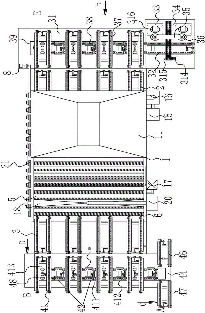
[0026] refer to Figure 1 to Figure 8, the present invention includes a tank body 1 provided with a feed belt 2 and a discharge belt 3, the feed belt 2 and the discharge belt 3 are double rows, and the feed belt 2 and the discharge belt 3 are evenly spaced Horizontally arranged at both ends of the pool body 1, one end of the feed belt is provided with a uniform sheet distribution mechanism, and one end of the discharge belt is provided with a silicon chip collection mechanism, and the pool body 1 is from the feed belt 2 to the discharge belt. 3. A corrosion pool 4 and a cleaning pool 5 with a housing chamber are arranged in the direction. The corrosion pool 4 and the cleaning pool 5 are provided with several conveying rollers 6 placed horizontally in the housing chamber. The conveying rollers 6 are driven by a timing belt 21 The transmission is connected together and connected with the driving motor 8. The conveying roller 6 is provided with a spiral 7 distributed along its sh...


PUM


Abstract

The invention discloses a phosphorosilicate glass removal processing production line for crystalline silicon solar cell processing. The phosphorosilicate glass removal processing production line comprises a pool body provided with a feeding belt and a discharging belt, wherein the feeding belt and the discharging belt are evenly and horizontally arranged on two ends of the pool body at an interval; one end of the feeding belt is provided with an even wafer distribution mechanism; one end of the discharging belt is provided with a silicon wafer collection mechanism; the pool body is provided with a corrosion pool with a containing cavity and a cleaning pool with the containing cavity; conveying rollers are in transmission connection via synchronous belts and are connected with a driving motor; each conveying roller is provided with screws distributed along the axle body of the conveying roller; a weep pipe above one conveying roller is arranged in the corrosion pool and is provided with a water outlet; multiple pairs of flushing pipes positioned above and below the conveying rollers of the cleaning pool are arranged in the cleaning pool; and each pair of flushing pipe is provided with symmetrical flushing holes. Compared with the prior art, the production line is characterized in that even wafer distribution and collection is realized, the production line can be prevented from being corroded by acid mist, a conveying roller structure is improved, vibration and hydrofluoric acid splashing can be avoided, and production quality and production efficiency are improved.

Description

【Technical field】 [0001] The invention relates to the technical field of crystalline silicon solar cell processing equipment, in particular to a dephosphorous silicon glass processing line for crystalline silicon solar cell processing. 【Background technique】 [0002] With the continuous improvement of solar cell production technology, new requirements are put forward for the quality and cost of solar cell products. Phospho-silicate glass must be removed for solar cell production for the following reasons: Due to the diffusion process in the manufacturing process of solar cells, even if back-to-back diffusion is used, all surfaces of silicon wafers including the edges will inevitably be diffused with phosphorus. The photogenerated electrons collected by the front side of the P-N junction will flow to the back side of the P-N junction along the edge-diffused region of phosphorus, causing a short circuit. [0003] In the manufacturing process of solar cells, phosphorus diffusi...

Claims


Application Information

Patent Timeline
Patent Type & Authority Applications(China)
IPC IPC(8): H01L31/18H01L21/677
CPCH01L21/6776H01L31/186H01L31/1876Y02E10/50Y02P70/50
Inventor 张仲英王斌孔维兴
Owner ZHEJIANG LVYUAN PV TECH
Learn More