Micro-fluidic chip device adopting coupling operation of two drive modes for syphilis diagnosis

A technology of microfluidic chip and driving mode, applied in the field of analysis and testing, can solve the problems of troublesome operation, large flow resistance, and distortion of the inner surface modification of PDMS microchannels.

Inactive Publication Date: 2016-11-23
NINGBO UNIV
View PDF2 Cites 1 Cited by
  • Summary
  • Abstract
  • Description
  • Claims
  • Application Information

AI Technical Summary

Problems solved by technology

[0007] But it's not that simple
[0008] First, this polydimethylsiloxane material, the material referred to by the acronym PDMS, is itself a strongly hydrophobic material. Microchannels are built on this material. If the microchannels are not targeted The modification operation of the surface of the channel, then, after the overall assembly is completed, that is, after the cover is covered, because the inner surface of the micro channel in the structure occupies most of the inner surface of the liquid flow channel, then the PDMS micro channel The strong hydrophobic characteristic of the inner surface of the channel is the decisive factor, which will make it very difficult for the polar liquid flow similar to the aqueous solution to pass through, and its flow resistance is so large that even ordinary micropumps are difficult to push. Of course, If the cover sheet also chooses to use the PDMS material, then the problem is basically the same, with little difference; therefore, in the prior art, it is necessary to modify and modify the inner surface of the microchannel on the PDMS material; then , is this modification operation for the inner surface of the PDMS microchannel very troublesome? That's not the problem. What constitutes a serious technical problem is another problem: the PDMS polymer molecules in the bulk phase of the PDMS material substrate have the characteristics of automatic diffusion and migration to the surface. The characteristics of polymer molecules diffusing and migrating to the surface automatically will make the modified state of the inner surface of the microchannel modified by the surface modification unable to maintain for a long enough time, and the microgroove after surface modification The maintenance time of the inner surface state of the channel is roughly only enough to complete the time required for the internal test experiment in the laboratory; in other words, the inner surface of the PDMS microchannel after surface modification or surface modification is formed after modification The surface state of the surface does not last long, but quickly tends to or changes back to the surface state before the surface modification, and returns to the original strongly hydrophobic surface state in a relatively short period of time. Then, just imagine, Can such microfluidic chips be produced in large quantities, stored in large quantities, and widely promoted? The answer is obvious, that is, impossible
[0016] Third, as mentioned above, the inner surface of the PDMS microchannel is strongly hydrophobic, and targeted surface chemical modification or surface chemical modification is difficult to last. It is effective to use it within a short period of time; if the relatively short expiration date has passed and it is still used forcibly, since the surface state is already close to the hydrophobic state, there must be a comparison between using the conventional micropump to drive the sample liquid flow. Large flow resistance, in this way, the sample liquid can only be forced to flow in the target direction by increasing the pumping power and pumping pressure of the micropump. Pumping pressure to pump the sample liquid flow will cause bubbling, puffing, twisting, and deformation of the microchannels at the sampling end of the substrate including the area near the sampling end, and, under such high pressure conditions, The microgroove and its periphery at the sample inlet and its vicinity are also prone to peeling between the substrate and the cover slip. In this case, the sample solution will enter between the substrate and the cover slip formed after the peeling. This actually leads to the damage of the microfluidic chip; of course, if the surface modification or the surface modification is not in place, it will also lead to the above-mentioned situation within the short customary validity period; In the case of simply using an external micropump for liquid flow drive, the above-mentioned problem always exists
As mentioned above, if no pre-operations such as surface modification or surface modification have been done at all, then the above-mentioned problem will be more serious, even if the microchannel bubbling at the injection end and its vicinity does not occur , puffing, twisting, deformation, and peeling between the substrate and the cover sheet, etc., just because the flow resistance is too large, the use of a high-pressure micropump may not be able to drive the sample liquid flow toward the terminal.

Method used


Image

  • Micro-fluidic chip device adopting coupling operation of two drive modes for syphilis diagnosis

Examples


Embodiment Construction

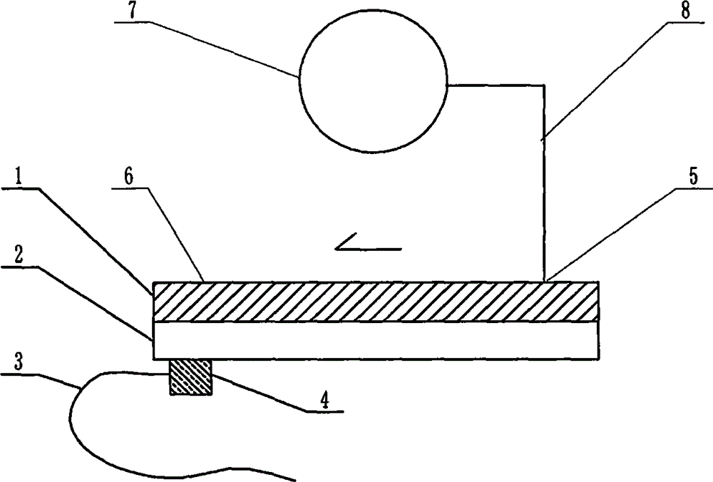
[0052] exist figure 1 In the shown embodiment of the present case, the structure of the device includes a multi-channel microfluidic chip, and the structure of the microfluidic chip includes a substrate 1 and a cover sheet 2 that are attached to each other and installed together. The substrate 1 and the cover sheet 2 are plates or sheets, the surface of the substrate 1 facing the cover sheet 2 contains a channel structure formed by a molding process or an etching process, and the substrates that are attached to each other The sheet 1 and the cover sheet 2 jointly construct a microfluidic chip with a pipe structure, and the structural position of the pipe is located at the junction area where the substrate 1 and the cover sheet 2 are attached to each other. The two ends of the pipe are respectively connected to the The sampling port 5 of the microfluidic chip is connected to the terminal 6, the sampling port 5 is the injection port of the sample solution of the microfluidic chi...


PUM

PropertyMeasurementUnit
Diameteraaaaaaaaaa
Lengthaaaaaaaaaa
Thicknessaaaaaaaaaa

Abstract

The invention relates to a micro-fluidic chip device adopting coupling operation of two drive modes for syphilis diagnosis and belongs to the field of analysis and testing. Aiming at solving the problems caused by adoption of cheap and easy-to-process PDMS (polydimethylsiloxane) for manufacturing a substrate of a micro-fluidic chip for syphilis diagnosis, the scheme is characterized in that the substrate adopts PDMS with an original surface, a miniature ultrasonic transducer is fixedly mounted in the position adjacent to a sample liquid flow terminal of the micro-fluidic chip, interfacial tension is reduced through ultrasonic waves, meanwhile, the ultrasonic intensity is reduced progressively and rapidly in a short distance on the basis of high ultrasonic absorption capacity of PDMS, so that interfacial tension difference is formed between two ends of the chip, and power for driving sample liquid flow to flow towards the terminal along a hydrophobic capillary channel is provided by the difference and is mutually supported, mutually coupled, mutually adjusted and mutually cooperative with mechanical pumping power of a micropump in the structure simultaneously.

Description

technical field [0001] The invention relates to a microfluidic chip device for syphilis diagnosis, which is referred to as a coupled operation of two driving modes in this case, and belongs to the field of analysis and testing. Background technique [0002] For the technical background of multi-channel microfluidic syphilis diagnosis, please refer to CN 200910160439.X and other invention patent applications. [0003] As far as the overall overview of microfluidic technology itself is concerned, you can refer to the monograph "Illustrated Microfluidic Chip Laboratory" published by the famous microfluidic expert Mr. Lin Bingcheng not long ago, which has been published by Science Press. The past, present, and future prospects of microfluidic technology, etc., have detailed and long-form discussions that go deep into specific details. [0004] So, let's talk about the key issues of this case. [0005] The basic structure of a microfluidic chip includes a substrate etched with ...

Claims


Application Information

Patent Timeline
IPC IPC(8): G01N33/571
CPCG01N33/571G01N2800/70
Inventor 李榕生吴大珍李天华雷克微王叶干宁何佳丽朱云云
Owner NINGBO UNIV
Why Eureka
Try Eureka