
A vacuum tube furnace system

A vacuum tube furnace, bellows technology, applied in furnaces, muffle furnaces, cooking furnaces, etc., can solve problems such as poor air pressure accuracy and stability, needle valve blockage, affecting air tightness, etc., to achieve accurate air pressure control, reduce Air pressure fluctuation, the effect of improving accuracy

Active Publication Date: 2018-04-24
SOUTHEAST UNIV
View PDF7 Cites 0 Cited by
  • Summary
  • Abstract
  • Description
  • Claims
  • Application Information

AI Technical Summary

Problems solved by technology

[0003] Existing technology mainly uses two different types of pumping channels, one with standard KF16 or KF25 diameter, which is usually used in high vacuum conditions, and the control accuracy is poor in low vacuum; the other is connected with plastic pipes, only Can achieve lower vacuum
However, in practical applications, a wide range of adjustments is often required. When the conditions vary greatly, only different pumping channels can be replaced, which brings inconvenience to experimental operations and differences in growth parameters.
The working tube interface of the prior art adopts customized parts, which has poor versatility, high cost, poor precision, and poor airtightness
In actual use, the air pressure is mainly controlled by the opening state of the manual adjustment valve, the accuracy and stability of the air pressure are poor, and repeated adjustments are required to maintain a specific air pressure
In addition, in an environment containing dust in the atmosphere, the dust is easy to block the pipeline, causing the narrow places such as the needle valve to be blocked, and even the needle valve needs to be disassembled for cleaning after 2-3 times of use. The tightness may also cause changes in specific instrument parameters, thereby affecting the accuracy of the device

Method used


Image

  • A vacuum tube furnace system
  • A vacuum tube furnace system

Examples


Embodiment Construction

[0019] The technical solutions of the present invention will be further described below in conjunction with the accompanying drawings, but the scope of protection claimed by the present invention is not limited thereto.

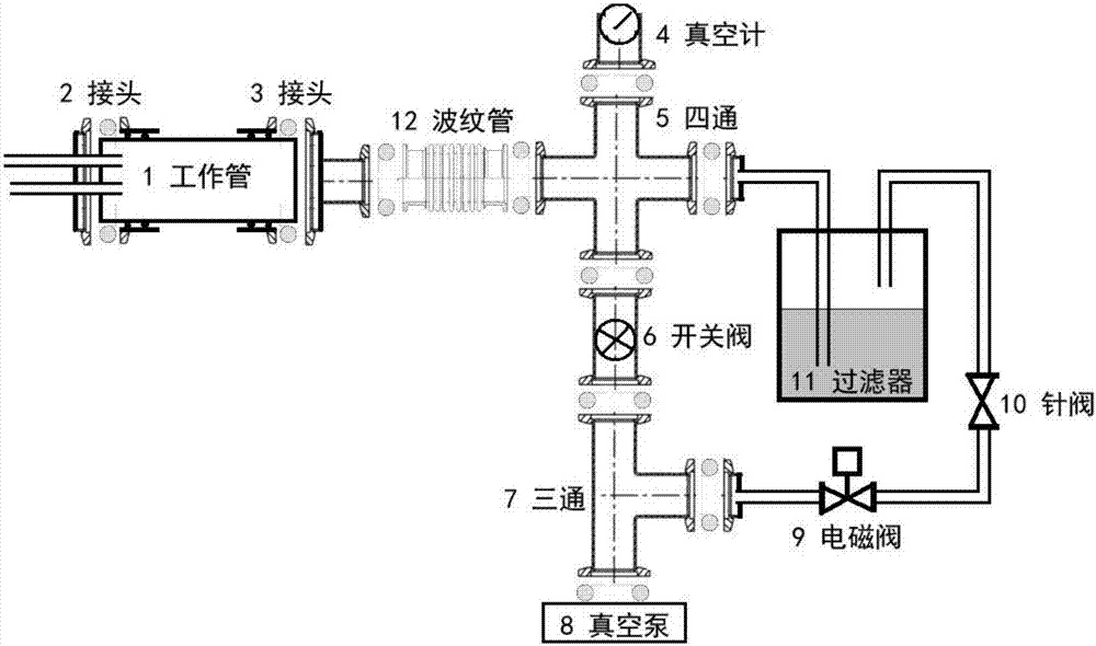
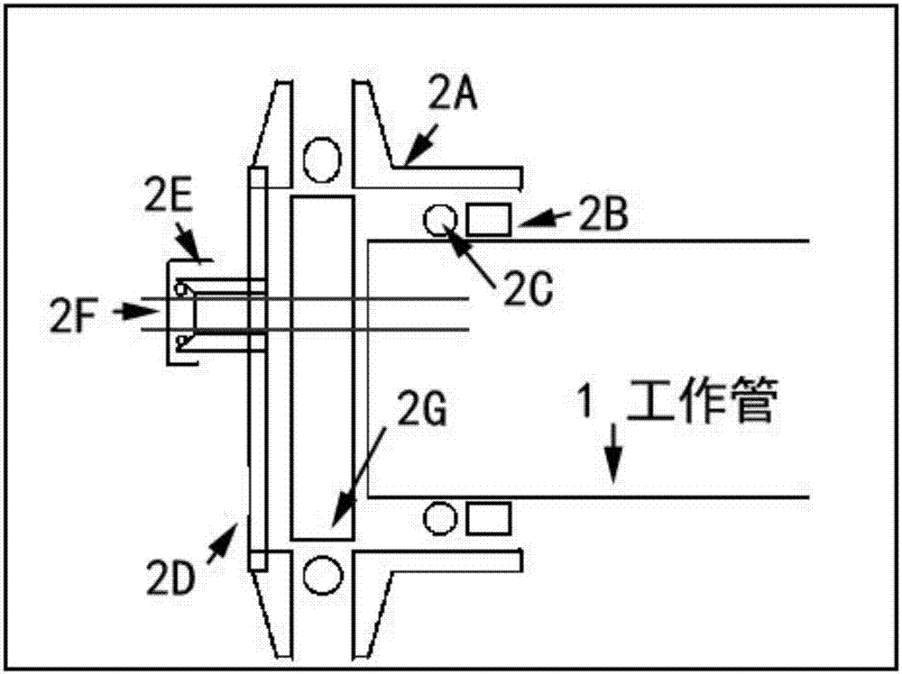
[0020] Such as Figure 1~2 As shown, the vacuum tube furnace system of the present invention includes a working tube 1, a corrugated tube 12 and a four-way tube 5 connected in sequence. One end of the working tube 1 is connected to the intake pipe through the inlet joint 2, and the other end of the working tube 1 is connected to the air intake pipe through the suction port. The end joint 3 is connected to the corrugated pipe 12, and the passage formed by the working pipe 1, the bellows 12 and the four-way pipe 5 is divided into two branches by the four-way pipe 5, and the first branch passes through the switching valve (ball valve) 6 and the three-way pipe. 7 is connected to vacuum pump 8, and the second branch is connected to vacuum pump 8 by buffer filter 1...


PUM


Abstract

The invention discloses a vacuum tubular furnace system. The vacuum tubular furnace system comprises a working pipe, a corrugated pipe and a four-way pipe which are sequentially communicated, wherein one end of the working pipe is connected with an air intake pipeline through an air intake end joint, and the other end of the working pipe is connected with the corrugated pipe through an air exhaust end joint; a passage formed by the working pipe, the corrugated pipe and the four-way pipe is divided into two branches by the four-way pipe; the first branch is connected to a vacuum pump through a switch valve and a three-way pipe; and the second branch is connected to the vacuum pump through a buffering filter, a needle valve, an electromagnetic valve and a three-way pipe. The vacuum tubular furnace system further comprises a barometer used for measuring an air pressure in the passage, and a circuit automatic control system. Two air exhaust passages are adopted in the vacuum tubular furnace system disclosed by the invention, so that wide-range adjustment for an air exhaust capacity can be realized, and the air pressure can be accurately controlled in a wide range; in addition, the system realizes automatic control and adjustment for the air pressure by virtue of the electromagnetic valve and the buffering filter; and the vacuum tubular furnace system disclosed by the invention is good in air tightness, accurate in air pressure control, and capable of being used in an atmosphere rich in dust.

Description

technical field [0001] The invention relates to a vacuum tube furnace system, which belongs to the field of devices for material preparation and atmosphere heat treatment. Background technique [0002] Vacuum tube furnace systems are widely used in the fields of nanomaterial preparation, material atmosphere treatment and vacuum annealing. Vacuum tube furnace system is one of the most commonly used equipment for preparing nanomaterials by physical vapor deposition and chemical vapor deposition. A good vacuum tube furnace system requires features such as good sealing, precise adjustment, high stability, and easy replacement of working tubes. [0003] Existing technology mainly uses two different types of pumping channels, one with standard KF16 or KF25 diameter, which is usually used in high vacuum conditions, and the control accuracy is poor in low vacuum; the other is connected with plastic pipes, only A lower vacuum can be achieved. However, in practical applications, a w...

Claims


Application Information

Patent Timeline
Patent Type & Authority Patents(China)
IPC IPC(8): F27B5/05F27B5/06
CPCF27B5/04F27B5/06
Inventor 洪昆权王文达曹广霞郭皓文
Owner SOUTHEAST UNIV
Learn More